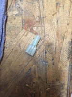
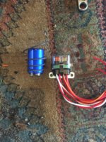
Dont cheap on your wiring. Run a ground wire up to where your ground bolt is and attach it with all other grounds and the battery ground. If you make a bunch of chassis grounds you’ll be chasing electrical gremlins all the time.
-
Enjoy XS650.com? Consider making a donation to help support the site.
XS650.com receives a small share of sales from some links on this page, but direct donations have a much greater impact on keeping this site going.
You are using an out of date browser. It may not display this or other websites correctly.
You should upgrade or use an alternative browser.
You should upgrade or use an alternative browser.
Wiring from Scratch
- Thread starter figure8
- Start date
member3480
RICH
I am working with two guys now and they both have wiring issues but they are getting there. One is doing it with the Black box and looks like its bad and the other had everything going great now no spark from the Pamco. So you may think you are doing everything correct and it still don't work. I always hook up STOCK/PAMCO/BOYER last because I know I am going to be testing lights brake switches horn charging wires and you don't want to leave power on your ignition for long periods without running.
I supply my phone number and they know they can call me 7 days a week and I will get back. Plus I have facetime on my phone so we can fix LIVE. I can see what you see.
Soon as I have time I plan on doing a do it yourself wire setup for bike. I have done it on facetime for guys
I supply my phone number and they know they can call me 7 days a week and I will get back. Plus I have facetime on my phone so we can fix LIVE. I can see what you see.
Soon as I have time I plan on doing a do it yourself wire setup for bike. I have done it on facetime for guys
I will concede the advice given and run grounds to battery or cap.
I do have a question I'd like to ask, in particular about the female connectors I'm gonna need to use from the Pamco to the coil. The wires from the Pamco plate I believe are 22 gauge, then from the red out on the coil I'll combine it with a 16 gauge. So I'm thinking of soldering the 16 and the 22 together then crimp it in a 14-16 gauge female connector then put a little shrink wrap over it over the crimped area. Sound ok? Pic for reference.
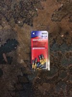
I do have a question I'd like to ask, in particular about the female connectors I'm gonna need to use from the Pamco to the coil. The wires from the Pamco plate I believe are 22 gauge, then from the red out on the coil I'll combine it with a 16 gauge. So I'm thinking of soldering the 16 and the 22 together then crimp it in a 14-16 gauge female connector then put a little shrink wrap over it over the crimped area. Sound ok? Pic for reference.

You might be better off getting water proof/insulated ones?
Yep that's better...I prefer the raw connectors, where you can add various sheathing, but those require a special crimping tool etc... which can be a little more expensive (you can get some super water proof/fancy ones too). But my feeling is to do it once, and know it's going to last.
However, if you're going with simple crimp versions (which work just fine)... then I like the heat-shrink versions like this:
http://www.amazon.com/Install-HSRMB-Shrink-Connector-100-Pack/dp/B005HQ4R6A
You can get them in different gauges, but once you crimp the wire on...you shrink the cover onto the wire. Works good. (The female version covers the connection obviously.)
I will concede the advice given and run grounds to battery or cap.
I do have a question I'd like to ask, in particular about the female connectors I'm gonna need to use from the Pamco to the coil. The wires from the Pamco plate I believe are 22 gauge, then from the red out on the coil I'll combine it with a 16 gauge. So I'm thinking of soldering the 16 and the 22 together then crimp it in a 14-16 gauge female connector then put a little shrink wrap over it over the crimped area. Sound ok? Pic for reference.
View attachment 62861
I use that type of connectors. I cut off the plastic insulators, crimp and solder, cover the crimps with shrink tube, females I cover the whole connector with shrink tube.
I wouldn't solder wires together before crimping.
I like to use the Harbor Freight little butane torch for soldering.
Scott
So a little update, I got some of the insulated connectors. The pic of the one I posted before was for very small wire so I used that for the green wire on the Pamco. These new ones I used to crimp the red from the Pamco to a lead out.
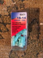
For the black on the Pamco I soldered a 16 gauge wire to it.
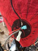
Then shrink wrapped it.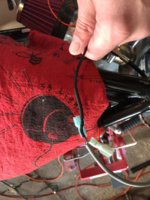
Once I know it's working right I'll go back and shrink wrap the red and green connections to the coil. Anybody seeing anything wrong here? For the lead out on the Pamco (red) we need to add a kill switch and 7.5 amp fuse per the diagram. Those will be going on next once I figure out where I want them to go. I'm thinking of using an inline fuse here.
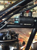
Lastly, for the engine ground I'm thinking I'll run a 12 gauge wire from the top engine mount of the frame to the top engine mount area on the engine with ring terminals. Sound good? Also, can anyone confirm the best type of grease to use on bare metal areas of the frame for grounds.

For the black on the Pamco I soldered a 16 gauge wire to it.

Then shrink wrapped it.

Once I know it's working right I'll go back and shrink wrap the red and green connections to the coil. Anybody seeing anything wrong here? For the lead out on the Pamco (red) we need to add a kill switch and 7.5 amp fuse per the diagram. Those will be going on next once I figure out where I want them to go. I'm thinking of using an inline fuse here.

Lastly, for the engine ground I'm thinking I'll run a 12 gauge wire from the top engine mount of the frame to the top engine mount area on the engine with ring terminals. Sound good? Also, can anyone confirm the best type of grease to use on bare metal areas of the frame for grounds.
And the engine is grounded to the frame.
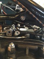
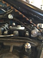
I used these terminals to do it then shrink wrapped them. Probably overkill on the 12 gauge wire but I had it so I'm using it.
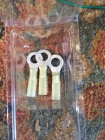
I should also note I'm using dielectric grease on the bare metal frame section until someone tells what a terrible idea that is and points me in the right direction, lol.


I used these terminals to do it then shrink wrapped them. Probably overkill on the 12 gauge wire but I had it so I'm using it.

I should also note I'm using dielectric grease on the bare metal frame section until someone tells what a terrible idea that is and points me in the right direction, lol.
Yeah, two camps on the di-electric grease, since it's not a conductor, I don't use it. The di-electric just brings to mind all of the charging problems on other peoples cars that I've worked on, once the Vaseline or grease was cleaned off of the battery connections the problem was usually gone.
Two camps on the top motor mounts too. I'll keep mine after finding one side loose and the other side broken on my stock mounts, I made a set of the custom jobs like TC Bros sells, I just think there is too much motor movement with or without them.
Scott
Two camps on the top motor mounts too. I'll keep mine after finding one side loose and the other side broken on my stock mounts, I made a set of the custom jobs like TC Bros sells, I just think there is too much motor movement with or without them.
Scott
Hi Scott,
true, dielectric grease ain't a conductor.
OTOH, I've found that it don't interfere with a terminal's conductivity so long as the terminal's surfaces are squeaky clean and they are done up tight.
What dielectric grease WILL do is keep the water out.
And although water IS a conductor (except for the super-pure water in nuclear reactor spent fuel bays) the nasty green crystals that grow in between wet terminal joints definitely AIN'T.
Hi Scott,
true, dielectric grease ain't a conductor.
OTOH, I've found that it don't interfere with a terminal's conductivity so long as the terminal's surfaces are squeaky clean and they are done up tight.
What dielectric grease WILL do is keep the water out.
And although water IS a conductor (except for the super-pure water in nuclear reactor spent fuel bays) the nasty green crystals that grow in between wet terminal joints definitely AIN'T.
Agreed, no grease where the connection is made, only on the outer parts, still, I won't use it.
Scott
I go back and forth on the top mount, I have one its just not on at the moment.
Noted on the grease.
As for wiring I just ordered a mini 4-way water proof fuse block from member scallywag. Should work nicely on this application.
http://www.bcpgarage.com/product/4-way-waterproof-mini-fuse-blocks
Noted on the grease.
As for wiring I just ordered a mini 4-way water proof fuse block from member scallywag. Should work nicely on this application.
http://www.bcpgarage.com/product/4-way-waterproof-mini-fuse-blocks
Yeah, really cool fuse block compared to what's available in the chain stores, please send me a couple. Like the subject and comments on your thread too.
Scott
Scott
Yeah, really cool fuse block compared to what's available in the chain stores, please send me a couple. Like the subject and comments on your thread too.
Scott
Thanks, use the code "giveaway" for %10 off. It was right around $19 shipped, already assembled.
pamcopete
Ride.Enjoy.Life is Simple
A note about grounding:
It's important to have a good ground between the frame and the engine even though they are bolted together. The dissimilar metals involved in the motor mounts and the engine can develop resistance. The PAMCO and other electronic ignitions have a ground to the sensor plate directly from the points housing and another ground from the box of tricks to the frame. This ground goes through the PC board in the box of tricks as well as the PC board of the sensor which creates a path for current from the battery or capacitor to the alternator or starter motor on the engine which would carry any current that is not carried by a bad ground between the engine and the frame. The problem is most evident with a starter motor when it draws large amounts of current from the negative battery terminal to the frame of the starter motor. This "leakage" current will pass through both PC boards of the ignition system and could either cause the ground track on the PC board to burn open or cause interference to the electronics in the box of tricks. In the case of a starter motor, the ground between the frame and the engine should be able to carry 100% of the starter motor current.
It's important to have a good ground between the frame and the engine even though they are bolted together. The dissimilar metals involved in the motor mounts and the engine can develop resistance. The PAMCO and other electronic ignitions have a ground to the sensor plate directly from the points housing and another ground from the box of tricks to the frame. This ground goes through the PC board in the box of tricks as well as the PC board of the sensor which creates a path for current from the battery or capacitor to the alternator or starter motor on the engine which would carry any current that is not carried by a bad ground between the engine and the frame. The problem is most evident with a starter motor when it draws large amounts of current from the negative battery terminal to the frame of the starter motor. This "leakage" current will pass through both PC boards of the ignition system and could either cause the ground track on the PC board to burn open or cause interference to the electronics in the box of tricks. In the case of a starter motor, the ground between the frame and the engine should be able to carry 100% of the starter motor current.
girard
XS650 Addict
A note about grounding:
It's important to have a good ground between the frame and the engine even though they are bolted together. The dissimilar metals involved in the motor mounts and the engine can develop resistance. The PAMCO and other electronic ignitions have a ground to the sensor plate directly from the points housing and another ground from the box of tricks to the frame. This ground goes through the PC board in the box of tricks as well as the PC board of the sensor which creates a path for current from the battery or capacitor to the alternator or starter motor on the engine which would carry any current that is not carried by a bad ground between the engine and the frame. The problem is most evident with a starter motor when it draws large amounts of current from the negative battery terminal to the frame of the starter motor. This "leakage" current will pass through both PC boards of the ignition system and could either cause the ground track on the PC board to burn open or cause interference to the electronics in the box of tricks. In the case of a starter motor, the ground between the frame and the engine should be able to carry 100% of the starter motor current.
Ok, to be honest, I am having a really hard time believing that a short length of copper "jumping out" the motor mount to the frame will be much different than a clean motor mount connection but you have much more experience in motorcycle wiring than I so I will go with your advice as well.
Where do people generally mount that jumper?
Thanks for the input Pete. I did a "mock" wire up of the Pamco through the fuse box to the cap as well connected cap to regulator to check if there was spark, there wasn't. So either my quick wire up was incorrect (I feel like I had it right) or the cap isn't working anymore. It hasn't been used in quite awhile so maybe it's gone bad? Should be noted when when I ran the Pamco straight to battery I had good spark.
pamcopete
Ride.Enjoy.Life is Simple
fig.8,
The capacitor does not hold a charge like a battery. It only acts as a filter for the pulsating output of the PMA and will hold a charge briefly as the load acts to discharge it in seconds.
The capacitor does not hold a charge like a battery. It only acts as a filter for the pulsating output of the PMA and will hold a charge briefly as the load acts to discharge it in seconds.
Similar threads
- Replies
- 4
- Views
- 102
- Replies
- 6
- Views
- 502
- Replies
- 28
- Views
- 2K

