Wiring from Scratch

fig.8,

The capacitor does not hold a charge like a battery. It only acts as a filter for the pulsating output of the PMA and will hold a charge briefly as the load acts to discharge it in seconds.


That makes sense, what does it imply that I wasn't getting a spark? I mean, I understand it can't hold a charge. I'm just confused a little...
 
Your fine girard, I have no issue with questions or input here.

Pete, sorry should've said I'm longer using an e-advancer despite my signature. I need to edit that.
 
Pete is correct and like I said before grounds are so important so that you do not damage your new parts or old ones. I use to thing because I am old that it was cool to just ground as you go along. Well after high tech electronics came to play on most motorcycles I learned the hard way and burnt up a bunch of parts and really looked at the frames and how they are grounded and just stepped it up a little when I started making harnesses for Harleys and the Jap bikes.
I burned up the very first PAMCO I ever owned in 15 mins of the install because I didn't read the direction and learned from that mistake to READ before I install.
Its very tough for someone who has no spares to figure out what is bad or not and I get emails all the time and they all say the same thing. IT WAS RUNNING FIND now I have no spark. A bad ground ,cheap lights, or just being a dumbass and walking away from bike with key on motor not running will do damage. I have a bike in my garage right now that guy decided to wash bike but listen to radio but kill switch was in the on position and he fried the stock pickup. It was only on for a hour or so he said. Well now a $250.00 DYNA is going in LOL.:doh:
 
Ok, to be honest, I am having a really hard time believing that a short length of copper "jumping out" the motor mount to the frame will be much different than a clean motor mount connection but you have much more experience in motorcycle wiring than I so I will go with your advice as well.

Where do people generally mount that jumper?

The operative words are "clean motor mount connection" which over time can actually act as a diode due to the electrolysis effect of current flowing through two dissimilar metals, in this case aluminum and steel. This same effect can also affect the separate ground wire, of course, but it is just easier to periodically clean the contact areas of the ground wire similar to what one does to the battery cables. Maybe TMX can add his usual in depth take on this esoteric subject.
 
The operative words are "clean motor mount connection" which over time can actually act as a diode due to the electrolysis effect of current flowing through two dissimilar metals, in this case aluminum and steel. This same effect can also affect the separate ground wire, of course, but it is just easier to periodically clean the contact areas of the ground wire similar to what one does to the battery cables. Maybe TMX can add his usual in depth take on this esoteric subject.

so its probably a good idea to run a seperate ground from the motor back to the post where everything is grounded. correct?
 
so its probably a good idea to run a seperate ground from the motor back to the post where everything is grounded. correct?

Yes. Some would say overkill, but considering the bikes in question are 40 years old, there has been plenty of time for electrolysis to have taken effect. And, your point is well taken because the same thing could happen to the battery cable to the frame. This is more applicable to a starter motor setup because of the very high currents involved, and it doesn't just apply to the PAMCO but any electronic device could be affected, such as the factory TCI which has a sensor on the stator and a box of tricks mounted on the frame.
 
.... Maybe TMX can add his usual in depth take on this esoteric subject.

Huh, what? (*blink*, *blink*) Uh-oh.

Okay, first, a quick take on 'dielectric grease'. Been using it since, like, forever.
This bottle of 'contact dope' was my dad's. It's almost as old as I am.
Used for servicing vacuum-tube electronics, and everything else since then.

GeneralCementContactDope.jpg

This is a good read on dielectric grease and application:

http://www.w8ji.com/dielectric_grease_vs_conductive_grease.htm
 
Thanks for chiming in Two Many, I'll give it a read.

Pete, in case you missed my question above. Can you help me?
 
Okay, grounds. An often ignored area, can cause the most bizarre of problems. 'Floating grounds', 'Ground loops', 'Intermittant grounds', 'Ground level voltages', 'Multi-point grounds', and 'Single-point grounds' are terms you'll hear in electronics bantering, especially where high currents share the same space as sensitive semiconductors.

Every conductor has some degree of electrical resistance, even a 1mm length of thick/solid silver wire.

With this in mind, consider that no matter how good your ground connections and wiring, the 'only' place that has the 'true' ground voltage is your battery's (-) negative terminal. Everywhere else in the grounding system will have some amount of voltage, increasing as the current increases. It's like being on a municipal sewer system. Enuff folks flush their toilets all at once, and here it comes up in your home.

Power supply and high-end audio engineers take this into account, and generally apply 'single-point grounding' in their designs, where all the various ground returns are independantly tied to a single spot, at or near the 'true' ground. That way, current dumps from one section won't jack with the ground-level voltage of another section.

Our older bikes, with their stable-voltage batteries, point and coil ignitions, mechanical regulators, and incandescent lighting, are quite tolerant of casual grounding. Has to get pretty bad before these start complaining.

Put modern semiconductor devices on these things, and the rules get tightened up. Although superior, single-point grounding doesn't have to be used everywhere, but consideration must be given to the ground return path of high current devices, like the electrical starter mentioned earlier.

The electric starter grounds thru its case, which is grounded to the bottom engine case thru its mount platform and bolts. So far, so good.

Suppose, for example, that the only reliable ground for the engine is thru the top motor mount, thru that short grounding pigtail. Not good. But it can be worse. The grounding path from the lower case to the top camcover (and its mount bosses) is best thru the cylinder studs. Can't really pass much current to the cylinder, there's a base gasket in the way. And, the head is somewhat isolated by the headgasket, some conductivity provided by the fire rings and 3 headbolts. With high currents, the ground potentials at various parts of the engine are now different.

Now consider an electronic ignition system, depending on its mounting in the cam endcover for its ground. During application of high starter currents, that cam endcover won't be at 'true' ground, and whatever voltage present at that point will be seeking ground as well, possibly trying to go backwards thru the device's semiconductors, onward thru the wiring.

It's not so much that this particular hypothetical scenario is important. What's important is the 'thinking' when designing ground return paths. For each ground, consider the serpentine path that must be taken for the return current, where are the weak points, will something else have to carry part of that current. And, don't assume something is grounded just because it's metal.

There's numerous ground fault/float/loop stories out there that make great object lessons.

One of my favorites was the mysterious chain of failures in certain automotive rear-end differentials. The rear axles had a short life, preceeded by the typical pinion/drive gear 'howling'. Drove the mechanics, and the warranty departments nuts.

It was found that these particular vehicles didn't have the complete 3-point grounding system: Battery to engine to frame. The ungrounded frame would have the frame ground currents seeking ground thru the only path available to them: Thru the rear suspension, to the axle housing, thru the axle bearings and pinion/ring gear, up thru the driveshaft, to the engine. Those ground currents were micro-welding the axle's differential parts.

There's many more stories. Maybe you've heard some as well...
 
Thanks for chiming in Two Many, I'll give it a read.

Pete, in case you missed my question above. Can you help me?

If I understood your question, you cannot run the ignition from the capacitor unless the engine is running and the PMA is working properly.
 
Twomany, I appreciate the input and thread bumps, I'll try my best to understand it. But of course it's painfully obvious I'm a newb in this regard. Not one to hang my head low, I'll keep this moving foward for the time being.

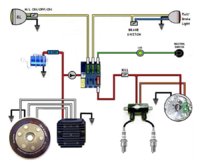
This crafty little fuse holder is a new puzzle to solve. Gonna throw the diagram back up to reevaluate.....
ImageUploadedByTapatalk1461218818.721104.jpg

Every lead on this fuse folder has of course one way in, one way out. For the "main" it leads to a 20A which is what I want. So my thinking is to have one of the leads go to the red from my regulator to 1 of 2 of the posts on my cap passing through the 20A fuse. These two wires to be exact...
ImageUploadedByTapatalk1461219226.775187.jpg

The other three leads one of which go through a 7.5A (Pamco) and the remaining 2 10A will go to the headlight and brakelight. My thinking is to combine these 3 wires into the other post on the cap. Respected switches will be put in place. Just want confirmation I'm on the right track,
 
Back
Top