XS650 Clutch Worm Actuator experiment & tidbits

This view approximates what the clutch worm would look like if viewed through the clutch cable opening in the cover.

Pic #1 - Original XS1B short-arm worm

Pic #2 - Modified offset longer-arm worm

Note the greater clearance to the sprocket.
Note the better angle provided to the clutch cable. Moved outboard, the cable has less of a turning angle to reach the lever/clevis.
 

Attachments

  • WormN01.jpg
    WormN01.jpg
    119 KB · Views: 557
  • WormN02.jpg
    WormN02.jpg
    163.6 KB · Views: 514
Just a side note. The factory cotter pin is just .040" (1mm) diameter, rather flimsy. A 1/16" (1.5mm) cotter pin fits nicely in the clevis pin, and seems more secure. Both cotter pins are in this pic.
 

Attachments

  • WormO01.jpg
    WormO01.jpg
    138.1 KB · Views: 351
Rigged-up a method to measure force required to move the clutch pushrod.

A brass button was made to fit over and protect the end of the clutch pushrod.
Then a fulcrum was fashioned, with a 1/4" steel rod taped to the backside of a piece of stiff wood, and bolted to the top two case screwholes.
A 3 foot angle iron is used as the lever.

Distance of pushrod to fulcrum pivot = 2.70"
Distance of weight guage to fulcrum pivot = 28.5"
Pull required to compress clutch pushrod to a distance of .050" - .080" = 35 lbs

This works out to about 370 lbs.

With 6 clutch springs, that's about 61 lbs per spring at this compressed position.
 

Attachments

  • WormO02.jpg
    WormO02.jpg
    178.3 KB · Views: 386
I'm sold. You should start production and sell them. Others have made lots of money for a lot less. They would be a gotta have for most 650 owners. I would buy one if the price was right. I will make one since I have what is needed to fab. Thanks great idea Two Manny. :thumbsup:
 
Hey, scabber, thanx. If you make one, post it up. I'm flailing around out here trying to come up with a method. I know you guys could do much better....
 
Pic #1 - The second version of the first experimental/re-bent worm is fitted to the case. It has a 1.7" clevis pin to worm center length, and a total drop from original height of 0.5" (as compared to 0.4" for the first iteration).

Pic #2 - With the clutch cable attached, the clevis pin is just a little over 4.1" from the reference hole in the cover. With the max leverage point at 3.7", and total effective cable travel of 0.6", this puts the max leverage at about 2/3rds of clutch lever travel.

Pic #3 - Clutch lever forces are measured at the lever end, inside the tip ball. Here, the pushrod adjuster screw is backed-out to measure the force of the return spring only, which shows about 14 ounces, almost 1 lb.

Pic #4 - All worm travel measurements are taken with a depth guage from a reference base to the steel worm body.

Results of this test:

Worm arm = 1.7", Lever force = 15 lbs, Worm travel = 0.055"
 

Attachments

  • WormP01.jpg
    WormP01.jpg
    168.6 KB · Views: 408
  • WormP02.jpg
    WormP02.jpg
    165.5 KB · Views: 382
  • WormP03.jpg
    WormP03.jpg
    134.1 KB · Views: 390
  • WormP04.jpg
    WormP04.jpg
    128.8 KB · Views: 395
Last edited:
I'll try to catch up on this later, but if it's a clutch improvement, my regular old clutch works fine, personally. What I would like is a cable where the steel goes all the way through the bead and out the other end and you can see it brazed there :) That way I'm confident it's not pulling out of the bead...
 
I used a brass thing like this for an emergency fix on my clutch when the cable had pulled out of the bead. Store next door had them.

http://www.themopedgarage.com/puch-cable-set

So then I ordered a Motion Pro cable because it never breaks, so of course three days later somebody posted up a picture of even one of those pulling out of its bead.
 
Which makes me think if there was a mechanical way to reduce the tension on the cable that would be useful.
 
I'm with ya on that, xjwmx, popped a few cable ends myself back in the day. My clutch was working fine, but been wanting to do this experiment for years. Right now, got the clutch cable tension value from 150 lbs down to almost 100 lbs. In an ideal frictionless environment, the cable tension here would be down to 50-65 lbs, so still experimenting...
 
I like the re-bent version. How did you do that? Did it require removing the arm from the worm?
 
I've been subscribed since the first post. :popcorn: Great stuff.

Doesn't hurt to check the whole system either.
ie frayed rusted cable (inside) I have had few that moved fine with no load but they would bind awful once they had to do some real work. I don't mess with a stiff cable very long, if it isn't free with some oil dribbled into it I toss it and put on new.

Clutch lever fulcrum bolt ruined augering out clutch lever.
Lubing this should be a standard maintenance item, moly grease is my choice. Do the brake lever too!

txwheel 003.jpg

Mikes sells the handle bolt complete for $1.10
 
I switched to a Kawasaki lever/perch assembly to gain a much wider lever pivot area .....

phDcC2H.jpg


No worries about wearing this lever hole out and it's a simple bolt-on swap.
 
Last edited:
I like the re-bent version. How did you do that? Did it require removing the arm from the worm?

I have 3 worms to play with. The first one has been bent into submission using a variety of sockets and scrap metal for support in the vise. Will post a more reasonable method later, after I get some plumbing pipe cut up. The second worm was disassembled and cut, offset arm welded on. It's on hold waiting for me to fill-in and redrill a hole. The third worm is my original factory replacement, in real good shape, unmolested, emergency spare.

Replaced literally hundreds of worn levers over the years, mostly bent/broken, but others from worn-out pivot holes. I like to 'bush' new levers before putting them into service, easier to center the hole for drilling when new...

http://www.xs650.com/forum/showthread.php?t=27152
 
Pretty happy with this new clutch action, ready to take it to the next level.

Whenever I manipulate the clutch, the clutch cable and elbow move a bit during slack take-up and settling into the casecover hole. This 'lost motion' eats up precious cable slack, and has always bothered me. So, decided to investigate.

Pic #1 - The infamous clutch cable elbow.

The cable on the top is a new factory '447' cable, the elbow is bent to a 30° angle.
The cable on the bottom is a new MikesXS cable, the elbow angle is 20°.
My old/installed cable, 16 years old, has a 20° elbow. Yamaha shop said it was the 'heavy duty' version, I assumed it was a factory cable.

Pic #2 - The new location of the modified worm arm clevis alters the cable entry angle by about 7-8°.

This creates an opportunity to improve the cable routing and action.
 

Attachments

  • WormQ01.jpg
    WormQ01.jpg
    154.5 KB · Views: 350
  • WormQ02.jpg
    WormQ02.jpg
    110.1 KB · Views: 405
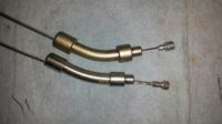
Properly routed clutch cables (routed from between the carbs) with 20° elbows don't quite fully fit against the casecover entry hole base, and wiggle/settle during slack take-up. The elbow will 'tip-up' and outward during settling into the casecover hole, creating unwanted lost motion. With the new/modified cable entry angle, the cable no longer needs a vertical entry angle, and actually exits the elbow at an unnecessary angle. This angle needs to change about 7-8°. The conundrum: Modify the elbow base, or the precious casecover. I'm pretty commited to this worm mod, so decided to modify the casecover.

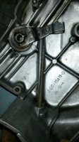
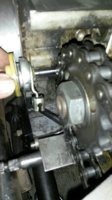
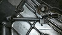
Pic #1 - The stock cable-elbow entry hole in the casecover provides the vertical fitment base for the elbow.

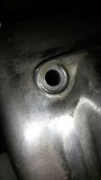
To get the 7-8° angle, about 0.70" needs to be removed from the inboard side of the entry hole base. This provides a 'cable aligned' fitment base for the elbow. A piloted 12mm recess cutter would be the ideal tool to use here, but did it by hand with a dremel instead. Must cut a little at a time, and check that the cut angle is correct.

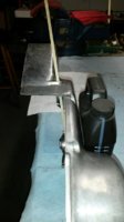
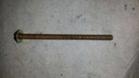
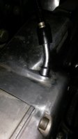
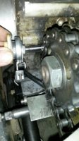
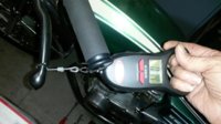
Pic #2 - The budget check tool, long 1/4" screw with 7/16" OD flatwasher.

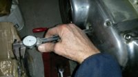
Pic #3 - Fit the 'budget' check tool onto the casecover hole, press it against the newly cut surface, and confirm that it points directly at the worm's clevis hole.

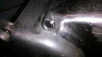
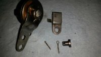
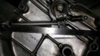
Pic #4 - The modified cable-elbow entry hole in the casecover.
 

Attachments

  • WormQ03.jpg
    WormQ03.jpg
    112.8 KB · Views: 385
  • WormQ04.jpg
    WormQ04.jpg
    149 KB · Views: 378
  • WormQ05.jpg
    WormQ05.jpg
    178.4 KB · Views: 558
  • WormQ06.jpg
    WormQ06.jpg
    129.1 KB · Views: 405
Pic #1 - The modified cable/elbow fitment, new entry angle almost noticable.

The properly routed clutch cable and 20° elbow fit with this new entry hole arrangement perfectly, as though it was factory engineered.

Pic #2 - During clutch activation, the cable and elbow don't move/settle at all, almost like the whole thing was welded in place.

Results of this mod:

Worm arm = 1.7", Lever force = 14 lbs, Worm travel = 0.057" (modified cable-elbow entry base)

Not much of an improvement to the clutch action, but a serious improvement to my pickyness...
 

Attachments

  • WormQ07.jpg
    WormQ07.jpg
    103.2 KB · Views: 373
  • WormQ08.jpg
    WormQ08.jpg
    140.6 KB · Views: 367
Last edited:
A bit on cables and 650 Central's schtick.

650 Central E-Z Pull Clutch Cable
Using an over-sized, nylon-lined housing, and a slinky 7x7 wound inner, this cable has sufficient free length to allow a proper leverage ratio at the push screw. Others don't. Also eliminates the friction-causing metal elbow. 1974-84. Black. For use with stock perches or our YZ lever assembly. The perches from Mikes XS are shorter and you'll have excessive free play.

Pullbacks, Tracker bars E-Z Pull 53 1/4" #FCEN26-3350......$19.95 ea.

Daytona, Euro, & shorter E-Z Pull 46 1/4" #FCEN26-3351......$19.95 ea.

Hi Bar, 15" Ape Hangers E-Z Pull 61" #FCEN26-3352....$19.95 ea.
 
Back
Top