That pin's on the rotor shaft, which I haven't removed. So I can't imagine it's slipping. And it'd have to be slipping 100% to produce 0 output, which is what I'm getting. Or, not getting.
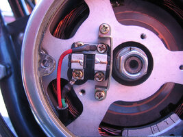
Nope... There's also a pin and slot arangement on the stator and engine case. A small slot in the stator and a pin sticking out on the cases. I'll venture as to say that if you didn't know that (you didn't) then you prolly didn't get it slotted correctly.