Looking for turn signal wiring kit

Squishman

XS650 Addict
Messages
150
Reaction score
179
Points
43
Location
Apple Valley, MN
I bought a wiring kit on Amazon that is terrible. The instruction sheet does not match the wire colors. And the components are more for a dune buggy it seems. Does anyone know of a good kit? I already have the lights I want to use. But I imagine a kit will come with lights. But I'll use the ones I bought already. If the kit includes a horn, that's even better.
 
I thought of that. But as far as the correct relay and what not, I don't have the knowledge to draw it up. I can follow instructions, can solder and crimp like a mofo but I am no engineer.
 
I would guess making your own would possibly be cleaner and simpler depending on how your bike is wired at the moment.

It would take more time but if the bike is clean, it’s worth it.

It’s really just a few wires and junctions.

Draw it out on paper first, then lay it out.

Go slow.
Indeed. There's loads of simple schematics out there on the internet. Just study them and build your own.
 
Pretty easy explanation.
This is so helpful man! I did get the kit already from Amazon, but I will use the video instead. The kit has some of the parts I'll need, but I'll snare the relays and flasher today! Thanks!
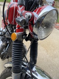
I did get couple of very cool turn signal relocators. Stainless steel, black. Top shock mount.
 

Attachments

  • Resized_Resized_20240331_142730.jpeg
    Resized_Resized_20240331_142730.jpeg
    318.7 KB · Views: 43
I have this speedo arriving today. https://www.amazon.com/dp/B07YMTRZZY?psc=1&ref=ppx_yo2ov_dt_b_product_details
It has an indicator light for the turn signals. Speedo turn signal indicator wires are: yellow wire is +, yellow/black is neg.
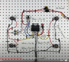
Can anyone tell me how to tie these in to the video wiring WingedWheel posted above? I have attached a screenshot of his super helpful wiring.
 

Attachments

  • youtube wiring.png
    youtube wiring.png
    581.7 KB · Views: 34
I am wondering if I can use the speedo indicator light, since I will be using 2 circuits. Seems I cannot.
I think you can do that. You use a diode in each feed to the single speedo indicator. You'll have two feeds into the indicator light (left side and right side). A diode prevents the left side signal crossing across to the right side and vice versa. Sorry, I'm not an electrician, but that is how I understand this issue. Hope that helps.
 
I think you can do that. You use a diode in each feed to the single speedo indicator. You'll have two feeds into the indicator light (left side and right side). A diode prevents the left side signal crossing across to the right side and vice versa. Sorry, I'm not an electrician, but that is how I understand this issue. Hope that helps.
It does! Hoping for specific connection info! And what diodes are needed.
 
Looks like (from what I see anyway) the diodes would be tied into the yellow from the relays.
If I understand correctly - One speedometer bulb terminal to ground. Other bulb terminal fed from yellow wire ×2. 1x diode in each feed to the bulb (2× diodes total). Think of a diode like a non-return valve. Others more expert than me will help you for sure.
 
If I understand correctly - One speedometer bulb terminal to ground. Other bulb terminal fed from yellow wire ×2. 1x diode in each feed to the bulb (2× diodes total). Think of a diode like a non-return valve. Others more expert than me will help you for sure.
Great! The picture gets clearer! I will need to know what diodes to get. I am like Sgt Schultz over here.
 
Back
Top