Making a two lobe points cam for single points conversion.
Keep in mind this ‘how to’ was written well after the fact, so, I may have missed some steps or got them slightly wrong. You’ll soon find out and you’ll soon have a bin full of useless cams. I was lucky first time around and got it spot on the first time. I’m currently making another, but as my patience grows thin, I’m expecting a few failures.
Material is your choice: My first was just mild steel, however, I’m currently visiting this work again, so, I’m using 304 stainless this time around. Stainless work hardens so, whilst the mild steel cam has worked OK, stainless should be better. Just be careful if using stainless, make sure you drill the central hole first, before any turning operations, otherwise you’ll burn out your drill bits and have irregular sized holes. Other materials to try are cast iron and Bronze or even tool steel if you are so inclined.
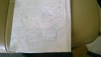
So, on to the work. Sizing is extremely important as it will affect the points gap. The gap is .13mm, so if you are out that means whilst one lobe will give you a gap of .13mm, if you are not exacting in your measurement, the other lobe gap could be much smaller or larger, thus affecting the timing of the cylinder that lobe feeds.
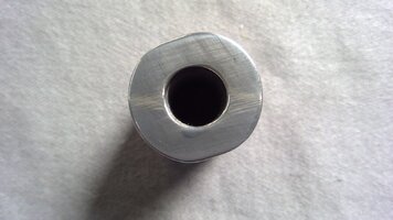
Ok, the hole in the centre of the stock is critical as that slides over the advance rod, you can’t afford any movement. Mount some stock in the three jaw and drill through with a 5/16” drill bit then follow up with an 8mm. The 5/16” bit is around 7.86mm actual bit size, if you follow up with the 8mm (7.93 actual) it will give you a hole of 7.97mm which just happens to be the size of the advance rod the cam slides over.. Keeping in mind, different materials react differently to drilling, so you might have to experiment with drill sizes. Also keep in mind, an 8mm reamer will give you an 8.00mm hole – too big!
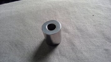
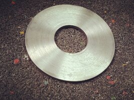
Next turn down the stock to 18.5/19mm and part off so the blank is roughly the same length as the stock cam. Then face both ends.
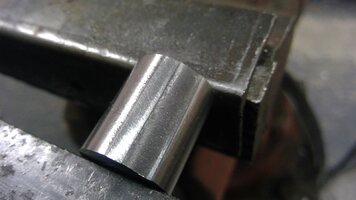
Mount the cam blank on the mill and using a 2.5 end mill, mill a slot around 6mm deep, then widen the slot so the pin in the advance shaft is a neat fit.
Whilst performing the following operations be sure not remove or disturb the advance rod or cam blank.
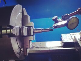
Chuck the advance shaft in the lathe four jaw and centre it by running the dial indicator on the bearing surface directly behind where the points cam is mounted., this must be exact, you cannot afford to me out by more than .01mm. Then place the cam blank on the rod and tighten the nut. The photo shows the dial indicator on the cam shaft area, but it'd be better off on the bearing surface as that dictates the concentricity of the cam.
Check the concentricy again using the bearing part of the shaft just behind the cam. Once centred turn down the blank to 18mm taking very fine cuts so you don’t disturb the concentricity of the shaft.
Once turned down to 18mm, smooth the blank by using 800+ wet and dry, then check the concentricity of the blank using a dial indicator, it shouldn’t vary by any more than .01mm.
That’s the easy part, now comes the hard bit.
Assemble the advance rod and cam on the bike and turn the points backing plate until it is centrally positioned and gap the points to .13 mm. Turn the engine over and check the points gap at different positions, shouldn’t be out by more than around .01mm.
Turn the alternator rotor around until the pointer is about 2-3mm before the first F mark and using a sharp blade run it across the cam blank just under the points heel. At this point, connect a test light or multimeter across the points.
Remove the blank, place it in the vice and file the ramp until the blank measures no less than 17.5mm from the flat you’ve just filed to the other side. Take care not to file the ramp past the scribed mark. Then with a file, file across the edge where the flat section meets the round part of the blank. You can use a micrometer here to help you creep up to .13mm, the points gap. Remove and replace the cam blank, filing away until the LED lights up.
That’s one lobe, now turn the engine over 180 degrees until the rotor mark is again about 2-3mm before the first F mark and repeat the process.
Dwell comes next, they say dwell should be as long as possible, however, I set the dwell to roughly where the light switches off when the timing mark is at 90 degrees to the F mark, that works fine for me. Not really that important.
Next you need to polish the cam to stop it wearing out the points heel. A nylon fibre wheel works best here, removing all the filing grooves, providing a nice shiny surface for the points heel to glide over and not removing too much material.
Remember the rotor pointer was set about 2-3mm before the F mark, now you need to fine tune the timing. The polishing should have removed enough material so the rotor pointer is very close to the centre of the F marks, if not, using the nylon fibre wheel polish the edge again, checking frequently until the light lights up when the rotor mark sits in between the two F marks.
A couple of extra points: Filing the ramps until the micrometer reads 17mm across them means the points heel will clear the ramps as the cam turns, this doesn’t really matter as the points are still closing, however, if you’re fussy and damn good with a file, you can round the ramps so the heel of the points sits closer to the ramp, thus lessening the slamming effect. This may increase the dwell also. That’s Ok though as they say a long dwell is better anyway.
A bit of a conundrum here: Having ramps much lower than .13mm will cause the points to slam shut, whereas having the ramps depth closer to the points gap will cause the points heel to wear more as the heel is in constant contact with the cam The original points cam ramp is under .13mm, so that’s a bit of a hint.
This time around, I’m going to try milling the flats and decreasing their depth to .25mm and see how a shorter dwell works out. Whatever size you choose, make sure it is enough for vagaries in points gap setting.
You can use the original points backing plate, but I thought it neater to make a new one.
You can make a backing plate quite easily. Shape a piece of 3 mm mild steel so you can get 62mm circle from it. Drill a 12 mm hole in the centre, stick a 12mm bolt through the hole and tighten it up.
Next clamp the bolt in the chuck and turn the plate down to 62mm and check it is a neat sliding fit in the points bucket, then drill the centre hole out to 24mm.
Place the old points plate over the new one and mark the holes for the points. The pivot is 4mm and the tapping hole for the clamping screw should be 3.2mm, then tap the hole with a 4mm tap.
Line the old plate over the new plate again and mark the cutouts on the circumference of the plate for adjustment and file them out. You have room for longer slots than the original plate,t hus giving you more adjustment.
You'll notice the points lead fixing screw sits very close to the points bucket. I moved the points holes on the new plate in a mm or so, for a bigger gap.
You can also make a timing LED quite easily using a 6mm lED. Button battery holders are available from any electronic shop, as are alligator clips, with these you can wire the LED straight to them as the 2032 batteries are 1.5 volts. If you use a 9 volt battery, like I use, you'll need to solder in a resistor.
Keep in mind this ‘how to’ was written well after the fact, so, I may have missed some steps or got them slightly wrong. You’ll soon find out and you’ll soon have a bin full of useless cams. I was lucky first time around and got it spot on the first time. I’m currently making another, but as my patience grows thin, I’m expecting a few failures.
Material is your choice: My first was just mild steel, however, I’m currently visiting this work again, so, I’m using 304 stainless this time around. Stainless work hardens so, whilst the mild steel cam has worked OK, stainless should be better. Just be careful if using stainless, make sure you drill the central hole first, before any turning operations, otherwise you’ll burn out your drill bits and have irregular sized holes. Other materials to try are cast iron and Bronze or even tool steel if you are so inclined.
So, on to the work. Sizing is extremely important as it will affect the points gap. The gap is .13mm, so if you are out that means whilst one lobe will give you a gap of .13mm, if you are not exacting in your measurement, the other lobe gap could be much smaller or larger, thus affecting the timing of the cylinder that lobe feeds.
Ok, the hole in the centre of the stock is critical as that slides over the advance rod, you can’t afford any movement. Mount some stock in the three jaw and drill through with a 5/16” drill bit then follow up with an 8mm. The 5/16” bit is around 7.86mm actual bit size, if you follow up with the 8mm (7.93 actual) it will give you a hole of 7.97mm which just happens to be the size of the advance rod the cam slides over.. Keeping in mind, different materials react differently to drilling, so you might have to experiment with drill sizes. Also keep in mind, an 8mm reamer will give you an 8.00mm hole – too big!
Next turn down the stock to 18.5/19mm and part off so the blank is roughly the same length as the stock cam. Then face both ends.
Mount the cam blank on the mill and using a 2.5 end mill, mill a slot around 6mm deep, then widen the slot so the pin in the advance shaft is a neat fit.
Whilst performing the following operations be sure not remove or disturb the advance rod or cam blank.
Chuck the advance shaft in the lathe four jaw and centre it by running the dial indicator on the bearing surface directly behind where the points cam is mounted., this must be exact, you cannot afford to me out by more than .01mm. Then place the cam blank on the rod and tighten the nut. The photo shows the dial indicator on the cam shaft area, but it'd be better off on the bearing surface as that dictates the concentricity of the cam.
Check the concentricy again using the bearing part of the shaft just behind the cam. Once centred turn down the blank to 18mm taking very fine cuts so you don’t disturb the concentricity of the shaft.
Once turned down to 18mm, smooth the blank by using 800+ wet and dry, then check the concentricity of the blank using a dial indicator, it shouldn’t vary by any more than .01mm.
That’s the easy part, now comes the hard bit.
Assemble the advance rod and cam on the bike and turn the points backing plate until it is centrally positioned and gap the points to .13 mm. Turn the engine over and check the points gap at different positions, shouldn’t be out by more than around .01mm.
Turn the alternator rotor around until the pointer is about 2-3mm before the first F mark and using a sharp blade run it across the cam blank just under the points heel. At this point, connect a test light or multimeter across the points.
Remove the blank, place it in the vice and file the ramp until the blank measures no less than 17.5mm from the flat you’ve just filed to the other side. Take care not to file the ramp past the scribed mark. Then with a file, file across the edge where the flat section meets the round part of the blank. You can use a micrometer here to help you creep up to .13mm, the points gap. Remove and replace the cam blank, filing away until the LED lights up.
That’s one lobe, now turn the engine over 180 degrees until the rotor mark is again about 2-3mm before the first F mark and repeat the process.
Dwell comes next, they say dwell should be as long as possible, however, I set the dwell to roughly where the light switches off when the timing mark is at 90 degrees to the F mark, that works fine for me. Not really that important.
Next you need to polish the cam to stop it wearing out the points heel. A nylon fibre wheel works best here, removing all the filing grooves, providing a nice shiny surface for the points heel to glide over and not removing too much material.
Remember the rotor pointer was set about 2-3mm before the F mark, now you need to fine tune the timing. The polishing should have removed enough material so the rotor pointer is very close to the centre of the F marks, if not, using the nylon fibre wheel polish the edge again, checking frequently until the light lights up when the rotor mark sits in between the two F marks.
A couple of extra points: Filing the ramps until the micrometer reads 17mm across them means the points heel will clear the ramps as the cam turns, this doesn’t really matter as the points are still closing, however, if you’re fussy and damn good with a file, you can round the ramps so the heel of the points sits closer to the ramp, thus lessening the slamming effect. This may increase the dwell also. That’s Ok though as they say a long dwell is better anyway.
A bit of a conundrum here: Having ramps much lower than .13mm will cause the points to slam shut, whereas having the ramps depth closer to the points gap will cause the points heel to wear more as the heel is in constant contact with the cam The original points cam ramp is under .13mm, so that’s a bit of a hint.
This time around, I’m going to try milling the flats and decreasing their depth to .25mm and see how a shorter dwell works out. Whatever size you choose, make sure it is enough for vagaries in points gap setting.
You can use the original points backing plate, but I thought it neater to make a new one.
You can make a backing plate quite easily. Shape a piece of 3 mm mild steel so you can get 62mm circle from it. Drill a 12 mm hole in the centre, stick a 12mm bolt through the hole and tighten it up.
Next clamp the bolt in the chuck and turn the plate down to 62mm and check it is a neat sliding fit in the points bucket, then drill the centre hole out to 24mm.
Place the old points plate over the new one and mark the holes for the points. The pivot is 4mm and the tapping hole for the clamping screw should be 3.2mm, then tap the hole with a 4mm tap.
Line the old plate over the new plate again and mark the cutouts on the circumference of the plate for adjustment and file them out. You have room for longer slots than the original plate,t hus giving you more adjustment.
You'll notice the points lead fixing screw sits very close to the points bucket. I moved the points holes on the new plate in a mm or so, for a bigger gap.
You can also make a timing LED quite easily using a 6mm lED. Button battery holders are available from any electronic shop, as are alligator clips, with these you can wire the LED straight to them as the 2032 batteries are 1.5 volts. If you use a 9 volt battery, like I use, you'll need to solder in a resistor.
Attachments
-
 3 timing lights.jpg190 KB · Views: 84
 -
 points backing plate2.jpg209 KB · Views: 63
 -
 points plate assempled.jpg433.2 KB · Views: 63
 -
 points plate fitted.jpg293.9 KB · Views: 90
 -
 polished points cam on rod.jpg163.3 KB · Views: 64
 -
 cam keyway end.jpg275.6 KB · Views: 60
 -
 polished points cam.jpg238.9 KB · Views: 58
 -
 polished points cam2.jpg212.5 KB · Views: 90
 -
 points cam comparo.jpg185.3 KB · Views: 59
 -
 IMG20230719140405.jpg335.9 KB · Views: 62
 -
 IMG20230621105105.jpg461.2 KB · Views: 57
 -
 IMG20230621111604.jpg620.5 KB · Views: 57
 -
 IMG20230621102327.jpg224.2 KB · Views: 64
 -
 IMG20230621103807.jpg299 KB · Views: 66
Last edited: