The 74 TX650 doesn't have the carbs linked, instead relying on a twin cable throttle, one cable for each carb. Adjustment to each carb via an small inline adjuster. This was obviously brain snap time at the Yamaha factory. What on earth made Yamaha think this was a good idea???
First I bought a single cable throttle, then looked around for a cable splitter but all I could find was a plastic thingy with no means of securing it, so it would just flop around inside the tank tunnel.
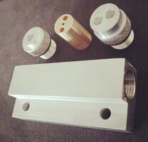
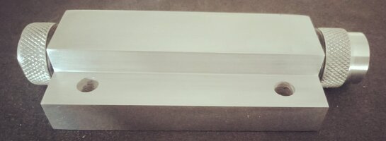
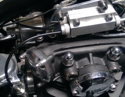
Didn’t like that idea, so I made one up from a small slab of ally. I bored a 14mm hole through the slab and ran a 5/8” UNF thread through each end on the lathe to a depth of 11mm. Next I milled a step and drilled two 6mm holes in the step for mounting it to the upper engine mounts. The two end caps are also aluminium turned up from some round stock. One has a one cable inlet, the other takes two cables. I ran a 5/8” UNF thread on them and then ran my scissor knurler over them. Both caps are fitted with O rings as the body will be filled with grease for lubrication.
The slide I made from brass, 14mm round, for a snug, sliding fit inside the main body, and 25mm long. Through this I drilled three 1.5mm holes, then countersunk them with a 3mm bit for the cable nipples. I then cut three slots with a slit saw in the slide, so the cables can be fitted.
Since it's under the tank, a polished finish was out, so I bought some acid and put together an anodising tank, using an old power supply, a 10 litre bucket and some aluminium cathodes. I put the splitter together and bunged the holes with rubber stoppers and dunked the thing in the bath. It came up very nice. I then mounted it to the top right engine mount.
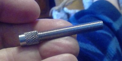
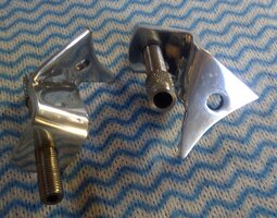
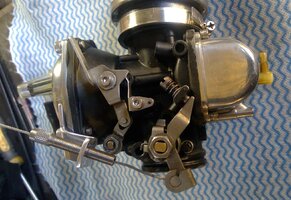
To make syncing easier I turned up some long, stainless adjusters for the cables, knurled them and made a couple of aluminium brackets to secure the adjusters to the top of the carbs. Then it was just a matter of making up three cables. Once done, I fitted it all together, started the bike and synced the carbs. Easy as.
Shortly after the diaphragms developed multiple holes, I wasn't about to spend money on carbs I rest, so the carbs were binned and replaced with VM34s. The VMs came with cables and a small inline splitter. My splitter won't work with the VMs as the the cable pull is too long. My splitter was made to suit the shorter pull of the BS38s. So now my splitter languishes in the useless parts drawer. I may make another down the track so I haven't got a splitter flopping around under the tank. Plenty of other stuff to play with first though.
This was a fun project and it worked well. Shame it now resides in the useless parts drawer.
A word on the anodising: This was my first foray into anodising so it was a learning curve. The power supply I used was an old Projecta battery charger which also functions as a power supply. Shortly after dunking the part and switching on the anodising process stopped functioning, assuming the Projecta was the problem I bought a 10 amp power supply and plugged that in, but, same problem. Eventually I traced the problem to the aluminium wire I used as a hanger. Being aluminium, it also attracted an anodised layer, isolating it from the part and anodising came to an abrupt halt. I tried titanium wire but that also failed. Eventually I used a wedge of wood to jam the wire against the parts, and found I also had to replace the wire occasionally. In retrospect, I should have opted for the 20 amp supply.