Operation Street Tracker

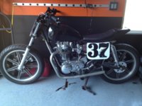
Well it is running so I will play with it slowly clean it up and ride it a bit to see what is all working and not. I am still hoping to complete the build on my 750 for the first street tracker out of the garage. Spent some time on here today got all of my tabs on for the inner fender and number plate, tacked the battery box up. I have some wire coming to do all of the wiring for my lights. Going to be mounting my solenoid, picked up some # 4 from the stereo dude for those home runs. I have to decide on the ignition location still wrestling with that one. Trying to get as far as I can in mock up before I have to tackle the motor dollars.

Does anyone know if it ok to have Pamco Pete's auto advance unit sitting in the same box with the battery?

How goes it with you Tracker Tim.
 
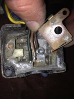
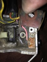
Quick wiring questions please on the hand controls the wiring on the left side when comparing my 82 to a 79 there is 3 less wires on the 79 that seem to have been attached to 3 contact posts under the rocker switch for the turn signals. Why are the wiring harnesses smaller? Self canceling? Wires just missing from PO?

The fist picture is the 82 and what looks like the wires went to, but they were undone when I went in which is common I guess, the second is showing the three wires, the third is the 79 without the 3 wires, how would the signals have worked without these three wires on the 79? Are they just missing from the hand control I found?
What are these three wires? Brown and white wire hot in from the flasher, green wire out to left signal, brown wire out to right signal?

What grounds do I need to run out of the left control to not rely on the handlebars for ground?

Thanks I ask because I am switching to the 79 controls with no choke and tring to remove what wires I don't need, and provide a ground wire. I am not using any of the rest of the stock wiring on the bike other than these controls, I have the Illuminator Pro III light control module that has the flasher and self canceling built in it. I am running all LED lighting. Thanks for any input.

Image.jpg

Image 1.jpg

Image 2.jpg

On the right side there was no ground on the 79 3 wires only so it must have grounded through the handlebars? The 82 has 4 wires one a black ground. I added the ground into the wiring on the 79 like the 82 is this ok? it is for the starter button to the solenoid I assume and I attached it where it was on the 82.
 
Last edited:
Big day today after a little over a year, buying a bike with only a bill of sale, I made it through the CHP VIN check and DMV I have title coming in a few weeks plates and tags in da house!!! Now I can get down to tearing this thing apart not having to worry and really going after getting the frame all completed and starting on the motor.
 
Nothing on any bike grounds through the handlebars ...:wink2: It could never ground satisfactorily because the bars are completely insulated electrically by the rubber bushes on the top yoke.

On the 79 ,the live feed to your signal switch is supplied from your self cancelling relay by a BrW brown white wire to the signal switch.
The self cancelling relay cuts the supply to the signal switch after a period thus cancelling the signals whether the signal switch is set to on or off.

(If you wanted to eliminate the self cancelling relay to simplify the wiring then all you need to do is to cut the yellow green wire from the self cancelling relay to the flasher relay and then connect a live feed to the yellow green wire going to flasher relay from one of your fuses that is switched live ( live when you switch the key on) and insulate the remaining yellow green wire from the self cancelling relay that you cut
You'll then have a separate power supply to your signal switch but thee self cancelling relay won't turn your signals off... naturally. )

From the 79 signal switch you have 2x wires out a DG dark green and a CH chocolate brown . One feeds 12v+ the right side signal lamps and signal indicator bulb and the other wire feeds 12v+ to the left hand signal lamps and the signal indicator bulb.
All the signal lamps ground themselves through their metal bodies to the fork headlamp brackets at the front and the fender at the rear.there is no seperate ground wire to the original signal lamps or to the signal switch .

On the 81 model your signal switch also has the wiring for your horn and your headlight which is why you have a 6xwire connector.
The black wire in the 81 switch goes to your reserve lighting unit and is not a ground wire for your signal switch. On the 81 and later the signal lamps have a separate black wire which goes to chassis ground unlike the 79 lamps which ground through the lamp body

Quick wiring questions please on the hand controls the wiring on the left side when comparing my 82 to a 79 there is 3 less wires on the 79 that seem to have been attached to 3 contact posts under the rocker switch for the turn signals. Why are the wiring harnesses smaller? Self canceling? Wires just missing from PO?

The fist picture is the 82 and what looks like the wires went to, but they were undone when I went in which is common I guess, the second is showing the three wires, the third is the 79 without the 3 wires, how would the signals have worked without these three wires on the 79? Are they just missing from the hand control I found?
What are these three wires? Brown and white wire hot in from the flasher, green wire out to left signal, brown wire out to right signal?

What grounds do I need to run out of the left control to not rely on the handlebars for ground?

Thanks I ask because I am switching to the 79 controls with no choke and tring to remove what wires I don't need, and provide a ground wire. I am not using any of the rest of the stock wiring on the bike other than these controls, I have the Illuminator Pro III light control module that has the flasher and self canceling built in it. I am running all LED lighting. Thanks for any input.


On the right side there was no ground on the 79 3 wires only so it must have grounded through the handlebars? The 82 has 4 wires one a black ground. I added the ground into the wiring on the 79 like the 82 is this ok? it is for the starter button to the solenoid I assume and I attached it where it was on the 82.
 
Last edited:
Had a little time today to go out in the garage and play man its been a while. I made me some foot rest brackets for some bear trap foot pegs. The pegs are off a KX 250 and cost $14 on ebay plan on just cutting off the old and welding on these should have a little more foot room.
IMG_1271.jpg

IMG_1272.jpg

IMG_1273.jpg
 
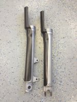
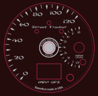
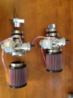
Ok its been a while I know, but had the opportunity to go up and meet Mike Morse at 650 Central I bought all of my brake rebuild parts, nickel plated chain and my carbs with the high VO manifolds and K&N air filters, and soft return springs, throttle cable and crank case breather. Got to watch and talk with Mike as he built up my set of carbs for my re-phased 750 build really cool and learned a whole lot about these carb set ups in the process. Also Uncle Ronnie came through with a set of carbon fiber fork guards for me things are looking up around here. I also completed the artwork for my GPS speedometer from Speed Hut the pink color is just where the dials go and not part of the gauge face but I got my name on there and our racing logo. I should be able to finish mock up now and get ready for making it pretty and a complete motor build :D. Here are some picture I know you guys only look at pictures so here you go.
IMG_1335.jpg

IMG_1336.jpg

IMG_1337.jpg

IMG_1318.jpg

IMG_1338.PNG
 
Nothing on any bike grounds through the handlebars ...:wink2: It could never ground satisfactorily because the bars are completely insulated electrically by the rubber bushes on the top yoke.

On the 79 ,the live feed to your signal switch is supplied from your self cancelling relay by a BrW brown white wire to the signal switch.
The self cancelling relay cuts the supply to the signal switch after a period thus cancelling the signals whether the signal switch is set to on or off.

(If you wanted to eliminate the self cancelling relay to simplify the wiring then all you need to do is to cut the yellow green wire from the self cancelling relay to the flasher relay and then connect a live feed to the yellow green wire going to flasher relay from one of your fuses that is switched live ( live when you switch the key on) and insulate the remaining yellow green wire from the self cancelling relay that you cut
You'll then have a separate power supply to your signal switch but thee self cancelling relay won't turn your signals off... naturally. )

From the 79 signal switch you have 2x wires out a DG dark green and a CH chocolate brown . One feeds 12v+ the right side signal lamps and signal indicator bulb and the other wire feeds 12v+ to the left hand signal lamps and the signal indicator bulb.
All the signal lamps ground themselves through their metal bodies to the fork headlamp brackets at the front and the fender at the rear.there is no seperate ground wire to the original signal lamps or to the signal switch .

On the 81 model your signal switch also has the wiring for your horn and your headlight which is why you have a 6xwire connector.
The black wire in the 81 switch goes to your reserve lighting unit and is not a ground wire for your signal switch. On the 81 and later the signal lamps have a separate black wire which goes to chassis ground unlike the 79 lamps which ground through the lamp body

Thanks peanut, I ended up running a ground wire into the control housing and I also inserted small springs on each side of the white signal indicator block to make the switch more self canceling on its own to work with the momentary requirements of the lighting module and LED's I have set up. I am making a complete wiring harness so I think I got it all squared away for now.
 
Don, are you using a o-ring or actual gasket between the intake manifolds and head? That groove is made for a o-ring IMHO. I got nothing from MMM when I bought my carbs and mani's. I searched around here for a o-ring that would work and didn't find anything suitable, except for a sealing washer in a pvc sink pipe kit I had. I didn't want to trust that.
 
Dave,
I have seen three variations of these now, I guess Mike kind of has changed machinist and they have been ever evolving I think. As such mine do not have the o-ring grove and Mike did supply me with gaskets. I think that the gasket may possibly a better setup with no gap at the manifold and the head for turbulence build up I am guessing. But a good tight fitting o-ring could do the same thing. It was pretty cool to watch listen and learn from a guy who knows what the hell he is doing. And to see his shop just chalked full of parts and one of his prized old road racers just makes you drool. I also learned something I did not know he never held a AMA pro license EVER, that probably makes him one of the most famous sportsman racers around.
 
Dave,
You are correct but, I'm not convinced that it is for an o-ring it would be a rather large diameter o-ring it appears that it would be between 1/4" and 3/8" diameter at least, that would stand the manifold off quite a bit. But it does look like it could be done with the right o-ring but I was given the gaskets for sure. A lot of carb and cleaner hanging off there to not have a good mating surface at the head seems like. I will not have any other supports or tie the carbs together either.
Image.jpg
 
Agreed on the size of the o ring needed. Cool pic Don. Saved!! I seen Chris Carr in one of his first if not first race at the TT. The Prince of Peoria. I think Dave Despain hung that on him. Used to talk with DD at Peoria and Springfield in the pits. Geez I'm getting old!
 
You guys are making me jealous. Stuck out here in the middle of nowhere with no good racing to be had. Shoot Sturgis was founded on the racing but that went away years ago.
 
Back
Top