An electronic TDC Finder and ConRod checker

Now, the findings.

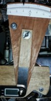
The pencil tracks show well defined piston position events.
TDC-Finder30.jpg


From each of the (4) events, draw radial lines down to the degree strip edge.
TDC-Finder31.jpg


Certainly doesn't look centered.
Overlay one of the smaller degree strips over the marked strip. Keep the 9" radius in alignment. Adjust the strip's position to get equal degree spacings from the event marks.
TDC-Finder32.jpg


Slowly rotate the crankshaft to get the pointer atop this new TDC position.

The tiny tic mark above the new strip's 1 degree mark is from the original degree strip's TDC location. Looks to be off by 1 degree.

Check the digital protractor.
TDC-Finder33.jpg


It agrees, off by 1 degree. The rotor mark is about 1mm left of the stator mark.
 
Last edited:
Now, to record the values.
Align the pointer with this new TDC. Zero the digital protractor.
TDC-Finder34.jpg


Slowly rotate the crank to the first (leftmost) event.
Looks to be 5.3 degrees on the strip chart. The digital protractor agrees.
TDC-Finder35.jpg


Slowly rotate the crank to the second event.
Looks to be 4.7 degrees on the strip chart. The digital protractor agrees.
TDC-Finder36.jpg


Slowly rotate the crank to the third event.
Looks to be 4.7 degrees on the strip chart.
The digital protractor shows 4.5 degrees.
TDC-Finder37.jpg


Slowly rotate the crank to the fourth event.
Looks to be 5.3 degrees on the strip chart.
The digital protractor shows 5.15 degrees.
TDC-Finder38.jpg


Remove the degree stripchart, note the findings.
TDC-Finder39.jpg
 
Now, the right cylinder.
Move the piston sensor to the right cylinder.
Do the same dry runs to get the sensor to settle-in, adjust its plunger stop.
Using the new TDC, affix a new degree strip, let it run.
TDC-Finder40.jpg


Looks to be off center again, but back the other way.
Extend the event lines, align and attach a thinner strip.
TDC-Finder41.jpg


Looks like it went back 1 degree.
Rotate the crank to this new right cylinder TDC.
Zero the digital protractor.
Interesting, the right cylinder TDC is spot on with the rotor mark.
TDC-Finder46.jpg


Find and record the (4) events.
TDC-Finder42.jpg TDC-Finder43.jpg TDC-Finder44.jpg TDC-Finder45.jpg

The right cylinder events.
TDC-Finder47.jpg
 
In both cylinders, the digital protractor appears to be off from my degree strips by about 0.2 degrees. I trust my degree strips, not so sure now about my budget digital protractor. I'll have to rig up a way to test that thing another time. For now, I'll just use the values from readings off the degree strips.

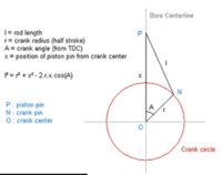
You can do web searches on "piston position", "rectilinear motion", and such to find simple formulas for determining piston motion geometries.
TDC-Finder48.jpg

A spreadsheet can be made using these formulas, to determine piston travel versus crank degrees, like this:

TDC-Finder49.jpg


At the bottom of this spreadsheet, I've plugged-in the event values, and get conrod slop values of 0.0017" and 0.0021". For now, the crank seems fine.
 
Another really interesting test Steve. Your creation is almost more interesting than the results. Some day in the future when we’re not around anymore, when the kids are all flying around on real hover boards, someone will pick up a box at a garage sale , look in it and see that contraption, and they’ll scratch their head and wonder. :umm:
 
...Another amazing project/creation 2M!

Thanx, Rob. It's the woodworking that's therapeutic.

Well... there is more than one way to skin a cat....;)
Nicely done Steve!!!

Thanx, Jim. My cats prefer this to the regular skinning.

Another really interesting test Steve. Your creation is almost more interesting than the results. Some day in the future when we’re not around anymore, when the kids are all flying around on real hover boards, someone will pick up a box at a garage sale , look in it and see that contraption, and they’ll scratch their head and wonder. :umm:

Thanx, Bob. That was the actual goal, future confusion.

I get these curiosities, and ideas, and get carried away with them.
Weird disease I guess.

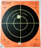
Long ago I had another wacky idea, and spent months designing/building a machine that allows me to modify rifle barrels, to improve accuracy. The process takes about 2 hours. Working with a budget Stevens 200, using budget ammo, it now shoots 1/4" groups at 150 yards.
Stevens200-223-01.jpg

Unfortunately, I can't figure out how to explain how this works...
 
Well, my thoughts were that if one were to rev the engine, then dump the clutch, the left half of the crank would try to twist forward, stressing the center shaft and its splines. I think that a 0.010" (0.25mm) twist displacement in the center crank splines would give that 1° offset.

Or, could just be manufacturing tolerances...
 
Back
Top