I recently claimed mine was bang on! But I would not be surprised if it is out by a couple of degrees. A will recheck in the next week by measuring about 15 degrees either side of TDC and then scribe to find the mid-point. I recently measured up the rotor relative to the timing marks and found that 1 degree error is approximately 1mm error on the timing marks.
-
Enjoy XS650.com? Consider making a donation to help support the site.
XS650.com receives a small share of sales from some links on this page, but direct donations have a much greater impact on keeping this site going.
You are using an out of date browser. It may not display this or other websites correctly.
You should upgrade or use an alternative browser.
You should upgrade or use an alternative browser.
An electronic TDC Finder and ConRod checker
- Thread starter TwoManyXS1Bs
- Start date
marvelous work 2M but I'm afraid I have never been able to see the point of attempting to achieve this level of accuracy over one tiny aspect of ignition timing on these lovely engines which lets face it are as far remote from being a precision machine as can be imagined.
I am a very firm believer in getting the absolute best out of any component that one can but there comes a point of fast diminishing returns, where the effort and cost far outweigh the miniscule benefit and our attention and investment would be far better spent improving many other aspects of these agricultural engines.
just my 2p worth
So, 2M's 2 degrees of error is moving his mark 2mm... I consider that signifigant.I recently claimed mine was bang on! But I would not be surprised if it is out by a couple of degrees. A will recheck in the next week by measuring about 15 degrees either side of TDC and then scribe to find the mid-point. I recently measured up the rotor relative to the timing marks and found that 1 degree error is approximately 1mm error on the timing marks.
Well, you're right, but what if yours was 4 degrees off, and you have no idea in which direction... I think it's worth the effort to find out...marvelous work 2M but I'm afraid I have never been able to see the point of attempting to achieve this level of accuracy over one tiny aspect of ignition timing on these lovely engines which lets face it are as far remote from being a precision machine as can be imagined.
Regarding TDC being out by 2mm: The significance of this depends on how you tune your engine e.g. 2mm could be the difference between knocking/pinging and no knocking if you use the stock timing marks as an absolute rule. But in TM's case I believe he runs his engine retarded and the level of retard is based on how the bike feels for his style of riding. I have recently changed to this style of tuning and enjoy a smoother ride so the "True" TDC position is only a guideline for me.
I made this change based on how the bike responded and felt when using fresh and old 95 octane compared to the fresh UK higher octane petrol. I noticed over this winter that half a tank of old 95 was much smoother than fresh 95 so drained the tank and filled with higher octane which also proved smoother running. Due to availability of higher octane I have decided to stick with 95 fuel and retard the engine to match the feel of higher octane fuel. I am currently moved 3mm to the right of the stock alternator timing marks i.e. retarded. I do not feel I have lost out on acceleration either and the bike is still starting easily.
I certainly agree with DogBunny in that it is important to know where TDC is so you have a built in reference to know where you are. I also take Peanuts point with regard to what degree of accuracy is necessary. I would love to know TDC within +/- 0.5 Degrees but believe I will only get to approximately +/- 1 Degree at best!
I plan to attempt to measure TDC far more accurately today so will feedback my findings later.
So, 2M's 2 degrees of error is moving his mark 2mm... I consider that signifigant.
Well, you're right, but what if yours was 4 degrees off, and you have no idea in which direction... I think it's worth the effort to find out...
thats just plain silly DB.....

Last edited:
I tried to use the U-Tube to determine TDC. Unfortunately the leakage through the ring gaps etc mess this method up. Damn, thought I was on to a winner. Next idea might be to insert a flexible strain gauge???
... the point of attempting to achieve this level of accuracy over one tiny aspect of ignition timing ...
Hey, peanut! It was mostly a curiosity thing. There's been some postings on inaccurate rotor marks on refurb and aftermarket rotors, and there's that strange revision to early XS1/XS1B timing. Why? Maybe the rotor marks were off? Dunno. And, yes, I'm also an oldschool tune by ear, feel, smell, taste. Put it where I like it.
But, that was only phase 1. The next part of this project may interest you.
Camping accessory.
I needed a place to slice and grill some deli meats...
2M ..I meant no criticism of what you are doing......I love following your little experiments.......... we learn so much.
You remind me a lot of the guy that broke down in the desert so he converted his car into a motorbike with a toothpick and some gaffa tape and drove out of the desert to safety .
You remind me a lot of the guy that broke down in the desert so he converted his car into a motorbike with a toothpick and some gaffa tape and drove out of the desert to safety .
I used to check and verify the TDC marks on these but don't too much anymore. They were all checking out OK so I kinda stopped doing it. I have the actual two stroke tool back from my old two stroke days. It's just like what Yamadude made up, a holder for a dial gauge that screws into the spark plug hole. With it, you can locate TDC exactly. Mine came from the Sears automotive catalog, of all places, lol. It's a quality tool in a nice wooden box. I'll have to get some pics.
Just because I don't use it much anymore, doesn't mean I've stopped completely. I will be checking/verifying the marks on the new bike me and my buddy are working on. Like many others here, I like running my timing a few degrees retarded. It wards off pinging and I think the bike runs very well this way. To accurately do that, I need to know if the marks are already off a few degrees. Maybe this might partly explain why one 650 seems to run a little better than another? Timing, even though set to the marks on both, may be different by a few degrees? Although some don't seem to, I do think accurate timing setting is very important. I also like exact and matched points gaps. That's why I use a dwell meter on points. I figure the best way to get the most out of your ignition is to set it as close as possible to the given specs.
Just because I don't use it much anymore, doesn't mean I've stopped completely. I will be checking/verifying the marks on the new bike me and my buddy are working on. Like many others here, I like running my timing a few degrees retarded. It wards off pinging and I think the bike runs very well this way. To accurately do that, I need to know if the marks are already off a few degrees. Maybe this might partly explain why one 650 seems to run a little better than another? Timing, even though set to the marks on both, may be different by a few degrees? Although some don't seem to, I do think accurate timing setting is very important. I also like exact and matched points gaps. That's why I use a dwell meter on points. I figure the best way to get the most out of your ignition is to set it as close as possible to the given specs.
I used to check and verify the TDC marks on these but don't too much anymore. They were all checking out OK so I kinda stopped doing it. I have the actual two stroke tool back from my old two stroke days. It's just like what Yamadude made up, a holder for a dial gauge that screws into the spark plug hole. With it, you can locate TDC exactly. Mine came from the Sears automotive catalog, of all places, lol. It's a quality tool in a nice wooden box. I'll have to get some pics..
Well I have a tool very much like Yamadude's that is made for setting the timing on old Tecumseh four-stroke engines. As the spark plug on those is not directly over the piston it has a "Z" shaped attachment on the dial indicator.
Well, I've got my new tablet up and running (kinda), so pick up where I left off.
This will take a while.
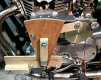
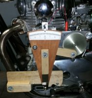
The pie-shaped board that's bolted to the crank is a 30° section of a 18" diameter timing wheel. Printed up some degree strips that will be attached to the fan board, aligned with a marked-up 9" radius.
With a radius of 9", 1 degree is 4mm wide, 1/4 degree is 1mm wide.

All I need is the outer degree portion, +/- 15 degrees.

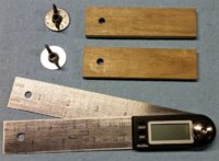
Printed a batch, and cut/trimmed for use.

The upper group of strips have an upper blank area that will be written on by a fine 0.5mm pencil, just like a strip chart recorder. The lower group of strips will be used to overlay the first strip, aligned with piston motion events, which will define true TDC.
This will take a while.
The pie-shaped board that's bolted to the crank is a 30° section of a 18" diameter timing wheel. Printed up some degree strips that will be attached to the fan board, aligned with a marked-up 9" radius.
With a radius of 9", 1 degree is 4mm wide, 1/4 degree is 1mm wide.

All I need is the outer degree portion, +/- 15 degrees.

Printed a batch, and cut/trimmed for use.

The upper group of strips have an upper blank area that will be written on by a fine 0.5mm pencil, just like a strip chart recorder. The lower group of strips will be used to overlay the first strip, aligned with piston motion events, which will define true TDC.
Minimal mussing with the bike for this.
Just remove both spark plugs, the round stator cover, and the rotor nut/lockwasher.
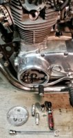
A large adapter nut replaces the rotor nut.
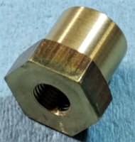
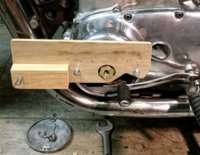
With its broad 1" head, it'll provide a solid mount base for the wooden degree fan.
Installed, torqued to only 15-20 ft-lbs.
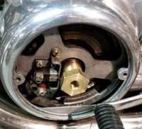
Set the crank to indicated TDC. We'll start with the left cylinder. To avoid fighting compression, have the opposite cylinder on the compression/power stroke. The left cylinder will be at TDC, on its overlap stroke, when the intake and exhaust valves are slightly open, and any compression trapped by the piston sensor will be vented. No concern about valve and sensor interference, since we're only going to rotate the crank less than +/- 15 degrees.
Just remove both spark plugs, the round stator cover, and the rotor nut/lockwasher.

A large adapter nut replaces the rotor nut.

With its broad 1" head, it'll provide a solid mount base for the wooden degree fan.
Installed, torqued to only 15-20 ft-lbs.

Set the crank to indicated TDC. We'll start with the left cylinder. To avoid fighting compression, have the opposite cylinder on the compression/power stroke. The left cylinder will be at TDC, on its overlap stroke, when the intake and exhaust valves are slightly open, and any compression trapped by the piston sensor will be vented. No concern about valve and sensor interference, since we're only going to rotate the crank less than +/- 15 degrees.
Last edited:
This is the drive unit. It will apply a slow and steady fore/aft motion to the degree fan board, eliminating the human element.
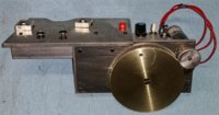
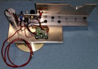
It uses a 12v high-torque gearmotor, geared down even slower, to get sweeps around 6 seconds per sweep. It has on/off and direction switches, and a PWM motor control.
This drive unit clamps rigidly to the head's largest cooling fin.
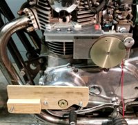


It uses a 12v high-torque gearmotor, geared down even slower, to get sweeps around 6 seconds per sweep. It has on/off and direction switches, and a PWM motor control.
This drive unit clamps rigidly to the head's largest cooling fin.

The degree fan board has a connecting rod, and a mount base for the optional digital protractor. The affixing rotor bolt has a hollow in its head, which accepts the protruding central post on the backside of the digital protractor.
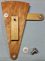
The degree fan board is bolted to the crank adapter, its connecting rod is attached to the large gear of the drive unit.
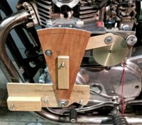

The degree fan board is bolted to the crank adapter, its connecting rod is attached to the large gear of the drive unit.

Last edited:
A transistor driven solenoid has a springy pointer finger, with a 0.5mm pencil lead in the pointer. It will move the pencil pointer up/down during piston position events.
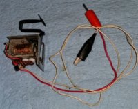
The red wire is a power plug-in, goes into the drive unit. The white wire goes to the piston sensor. Using a transistor driver allows the white sensor wire to use only a few microamps, avoiding any arcing and inconsistencies in the piston sensor.
The solenoid pointer unit is mounted atop the drive unit.
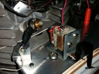
It's then connected to power and the piston sensor.
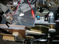
A degree strip is attached to the fan board, aligned with the 9" radius line.
Now comes the fun part. The crank must be set to its rotor's existing TDC mark. The degree strip and solenoid pointer need to be positioned exactly at TDC. The solenoid unit must also be positioned so that it's applying gentle pressure to the pointer's pencil lead, thru the pointer's thin spring brass. Triple check these alignments.
Turn on and zero the digital protractor.

Double check the degree strips alignment with the 9" radius line on the fan board, and the pointer's alignment on the strip's TDC mark.

With everything aligned, we're ready for the strip chart run.

The red wire is a power plug-in, goes into the drive unit. The white wire goes to the piston sensor. Using a transistor driver allows the white sensor wire to use only a few microamps, avoiding any arcing and inconsistencies in the piston sensor.
The solenoid pointer unit is mounted atop the drive unit.

It's then connected to power and the piston sensor.

A degree strip is attached to the fan board, aligned with the 9" radius line.
Now comes the fun part. The crank must be set to its rotor's existing TDC mark. The degree strip and solenoid pointer need to be positioned exactly at TDC. The solenoid unit must also be positioned so that it's applying gentle pressure to the pointer's pencil lead, thru the pointer's thin spring brass. Triple check these alignments.
Turn on and zero the digital protractor.

Double check the degree strips alignment with the 9" radius line on the fan board, and the pointer's alignment on the strip's TDC mark.

With everything aligned, we're ready for the strip chart run.

Last edited:
An exciting video. About as entertaining as boring cylinders.
Or, watching grass grow...
Or, watching grass grow...
The thing is left to run for a few minutes, to get a good pencil trace on the degree strip.
What I'm looking for here is not only true TDC, but the size of the gaps in the pointer's up/down movements, which could be a measure of the connecting rod's clearances.
I'm working with the following assumptions:
My experience with piston/ring fitment in cylinder bores says that there's enuff stiction/drag there to not only hold the piston/rings in the bore, but to also support the weight of the connecting rod. I don't believe there's enuff stiction/drag to lift the heavy crank, effectively eliminating its main bearings from this analysis.
This gadget is only applying fore/aft forces to the fan board, eliminating any up/down forces that could move the crank up/down.
So, the only clearances I'm expecting to be revealed would be from the connecting rod small end (wristpin to conrod, piston to wristpin), and from its big end bearing.
The clearances at the small end's wristpin are so small, plus being oiled, should be non-detectable. Unless they're worn, which this thing should detect.
So, I'm expecting only big-end clearances to be detected by this thing.
This post #29 in gggGary's crankshaft thread shows what I'm expecting in the range of big-end clearances:
http://www.xs650.com/threads/crankshaft-split-overhaul-assembly.31213/page-2#post-523057
Similar threads
- Replies
- 9
- Views
- 937
- Replies
- 20
- Views
- 4K


