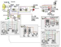
Curlys' electrical troubleshooting guide

nj1639

Paleo-simplistic
Top Contributor
Messages
4,199
Reaction score
3,429
Points
263
Location
Switzerland County, Indiana, U.S.A.
One of the best additions that you can put on yer bike, gave me a heads up to the electrical problem before it left me on the side of the road.
dustoff003.jpg
 
By relocating the key switch it allowed me to set the volt meter up between the clocks. I removed the light tree and moved the lights into the tach I found that had the turn, neutral and high beam indicator all under one glass. I trimmed off the upper part of the tree, it being unnecesary, and mounted the volt meter.

Here's a closeup of the switch mounted in place. The acorn nut to the left is the support, the one on the right is decorative ( symmetry- it's the English in me).

keyswitch001.jpg


Here it is hanging, shows a bit of where I filed and ground the back of the switch so's it'd fit flush. Also where I drilled through that frame tab to put the support bolt.
keyswitch002.jpg


The right side and the connecter. I just went into the bucket and found the connecter, brought it out and swung it down and around. It hides between the tank and the frame. Easy mod!
keyswitch003.jpg
 
Nice installation. Looks like factory. I gotta go dig out my tach and see if I have the three lights. It came paired with the same 0-120 speedo you have. Maybe I'll get lucky.

For my bike, I'm not so much concerned about having a volt meter, cuz I'll be having to install a Custom-Rewind rebuilt rotor anyway. I just like the cleaner lines, not having the light tree sticking up between the clocks.
 
One of the best additions that you can put on yer bike, gave me a heads up to the electrical problem before it left me on the side of the road.

Looks great, but deletes your steering lock and creates a three second hotwire job, also leaving you on the side of the road!
 
I agree fully with nj1639. I consider a voltmeter as essential equipment on these bikes..................you never know when the rotor or stator is going to quit. I want to know before leaving on a long ride rather than run out of voltage on the road. I like the ignition in stock location, so that I have the steering lock.
 

Attachments

  • 6622 mod 2.JPG
    6622 mod 2.JPG
    106.6 KB · Views: 273
This is a great guide, but I'm not there yet... Help!
I posted elsewhere about this... bought a 1978 XS 650 Special (what it says on the side cover) for damn near free.
Previous owner sez it "burned" a wire, he fixed it, and then later the harness went. I'm looking at this wondering where to start... have built custom HD's etc. so not a total noob, but the wiring is kind of "apart" at this point and the MC hasn't been run for 8 years or so. Still turns over, has some compression, etc.
I'm hoping to get some first steps suggestions (other than throw it in the river...).
The wiring harness is a total mess, it's been cut apart right below the headlight, wire sections added, and the wires twisted together and taped, not even soldered! It looks like it was lengthened or repaired or just really a pooch job.:wtf:
There are some burned/melted ground (black) wires... no other color wires seem to be trashed.
Is there a simplified wiring diagram I can use to at least get the bike running, so I can see if it's a rebuild candidate or a parts only machine?? I've seen some posted, but I'd really appreciate guidance per which one to use, mods needed, etc.
I'm reluctant to spend $$$$ before I know what's wrong/or right or left with this bike.
Thanks,
Les
 
With the wiring in that mess, your best bet is likely to buy a new harness from Mikesxs.com.

This is a basic wiring diagram that may help you.

You certainly will need to do a compression test sometime to see if the engine needs to come apart.
 

Attachments

  • XS650 all years.JPG
    XS650 all years.JPG
    103.9 KB · Views: 302
It seems to me that (1) you need to strip out the old wire and either (2) get a harness from Mike or whoever if you plan to keep the bike more or less stock or (3) run you own wires if you plan to chop or bob it. You need a few rolls of 14 ga in orange, brown, green, red, yellow and black.

I ran my own, soldered each connection, either shrink wrapped or Plast-Dipped the connections, bundled everything in flexible slit plastic conduit and zip tied it up neat. Used a Dremel wire brush to clean out the light sockets and dielectric grease where needed. Got a blade fuse block from Advance Auto Parts.

Its really no big deal, with a bobber or chopper you just need a few wires. A lot of the electrical paraophenalia on the stocker can be discarded (brake lining warning, headlight out warning, etc.) The only things I kept were the flasher, the starter relay (next to the fuse box in the pic) and the finned regulator that came with the SparkX alternator (mounted on the fender under the seat in second pic). ONce you throw away that extra junk, it will become clear how simple it is. THere are some good simplified elec diagrams here, hit the tech sections here and on 650Motorcycles.com for more advice and drawings. Go for it!

Rocket6.jpg


Rocket3.jpg
 
Thanks so much for the reply... yes, I thought I should toss the old harness... it's such a bad job of destruction...
I really appreciate the harness diagram, I'll use it to at least get the thing running (or to figure out what's fried, and what isn't).
Kent, nice job on yours, I'll start out by emulating your example, especially with the fuse block from Advance Auto. I've worked as an electrician in the past, and I appreciate neat and proper wiring!
Les
 
The wiring diagram that Retiredgentleman shows above (and which is referenced several times in the Tech section here) is almost perfect for my application -- except! No turn signals. I've been looking for a basically stock but simplified diagram for my 78E project that includes turn signals, the starter, and (hopefully) Pamco Pete's electronic iggy -- although I'm reasonably sure I can get Pete's system wired in without it being explicitly shown on the diagram. After looking at some of the other simplified diagrams that include turn signals, I'm thinking now it won't be too difficult to add them in.
 
Thanks, Les. Yeah, I've seen that one, or something like it. I like the detail of the one RG posted better because it shows things like the instrument lights. Welp, the Garage is a sister board anyway, isn't it? Don't see the harm in posting the link. Things are shared from this board over there as well.

My particular application is gonna involve some unavoidable custom wiring. On my cafe build, rather than running the stock handlebar switchgear, I've decided to buy one of the all-in-one switches made by K&S. Either their 12-0030 or 12-0040, haven't made up my mind yet.

http://www.kandstech.com/index.php?page=switchescontrols#

Plus, I'll be adding one of those 139dB Stebel air horns, which require their own circuit and relay. I have one on my BMW R90 and that sucker is LOUD! Loud enough for an SUV driving soccer mom on her cell phone with the windows rolled up to hear.

http://www.ridesafer.com/Stebel_Nautilus_Compact_Air_Horn_p/h0014-cah.htm
 
Back
Top