Voltmeter was bouncing between 10.9 and 11V within 2 blocks of leaving my house. Pretty disappointing considering I started it up just last night and marveled at how well it was charging at a mere 1500rpm. It was odd seeing as how the headlight was on. Perhaps a bad battery. I swapped in an AGM and now the light didn't even come on. Well, phucq, bad readings at the brushes (again). I pulled the rotor and measured open circuit resistance. Somewhere inside the coppery tumbleweed two ships weren't meeting in the night. After a trip to Crappy Tire to get a new tip for my soldering gun, I desoldered the leads to confirm they weren't just shorting out at the ends. No such luck. I swapped in my rotor of many fathers and got it running again, albeit a bit lazy on the charging, something this rotor has demonstrated from the get go. I sent off a rather spicy email to Rick's. They look good, but they are 0/2 now, and not cheap either. The keyway was also too deep, allowing the woodruff key to slide out between the bore of the rotor and the shaft, creating a very interesting removal experience. Smell ya later Rick's. Smell ya later forever.
-
Enjoy XS650.com? Consider making a donation to help support the site.
XS650.com receives a small share of sales from some links on this page, but direct donations have a much greater impact on keeping this site going.
You are using an out of date browser. It may not display this or other websites correctly.
You should upgrade or use an alternative browser.
You should upgrade or use an alternative browser.
First Ride Of The Season. First Charging System Failure.
- Thread starter MacMcMacmac
- Start date
Yeah, it's that time of year again. Guess I better get some copper wire on order.Feedback here says the reproduction rotors are junk, no matter where you buy them. An OE rewind should last forever. See @Jim
Well, I got it all apart and it seems one lead had cracked just where it does a 90 degree bend through the plastic spool. I managed to strip one winding off, get it all soldered up again and got a solid 5.9 Ohms. Now I just have to go replenish my 5 minute epoxy supply and slather on enough to choke a horse, or at least keep these leads anchored in place. I'll keep this rotor on the shelf for now.
The kind I use doesn't tolerate heat very well. I use heat or a hot blade to remove it. Choose wisely.5 minute epoxy
Well, I got it all apart and it seems one lead had cracked just where it does a 90 degree bend through the plastic spool. I managed to strip one winding off, get it all soldered up again and got a solid 5.9 Ohms. Now I just have to go replenish my 5 minute epoxy supply and slather on enough to choke a horse, or at least keep these leads anchored in place. I'll keep this rotor on the shelf for now.
That is an interesting repair ..Any pictures would be a step in a good direction
I Believe the copper wires ( Correct me if am wrong ) are lacquered to prevent shorts.
So if the lacquer is still there and the epoxy does not remove it
It is a fair chance it will work
Well, Jan is right, I should give a few details on how I disassembled the rotor.
I decided to repair the failed rotor that was sitting on the shelf today, so for the sake of general interest, here's what I did:

First, indicate on the back half pole shoes where the leads are located. This will get you in the ballpark, but to more accurately mark the proper location, I scribe a line on the back while it is assembled, or use an automatic punch and put a dimple as the seam where the two halve press together on the back.

Pull the face plate retaining screws. Luckily, I did not epoxy the in place this time. They can be a bear to get out, especially with Phillips heads. You can replace them with Allen head screws.

You can pop the face plate off the rotor body by gently prying under it with a flat blade screwdriver AFTER desoldering and removing the leads ( if still attached to the coil). This is a Rick's rotor, and they do not spare the laquer.

Here's the method I use when I don't have a hydraulic press. Support two pole "shoes" with a large piece of hexagonal, whatever... I happened to have two brass garden hose bits that worked well. This is a 3 1/2" vise and it was just barely able to support this Goldbergian setup. I recommend a piece of aluminum or copper to protect the snout of the rotor (...ahem).

Et voila! Once it gets moving, it doesn't take much to press it apart. On the hydraulic press I usually see only about 2 tons, which isn't much of a press fit at all, and is easily within the capability of most any vise. Or should I say vice, considering the Made in England on the side of mine.

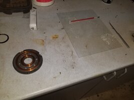
These are all the tools you need. My soldering gun is being camera shy... The can of carb cleaner is just photo bombing. I used some to clean up the mess from an earlier job.

Unfortunately, both leads had pulled off this time. This is likely fatal for this rotor, since it is the "foundation" lead at the very inner beginning of the winding. I may try to open up the bobbin to see if I can salvage this coil, but doing so without effing it all up seems dicey. This is the second Rick's rotor to fail like this. The last one I had seemed to lose its grip on the coil and it rotated inside the pole pieces, pulling the wires apart. I could move it by hand while it was hot. More epoxy!
I decided to repair the failed rotor that was sitting on the shelf today, so for the sake of general interest, here's what I did:
First, indicate on the back half pole shoes where the leads are located. This will get you in the ballpark, but to more accurately mark the proper location, I scribe a line on the back while it is assembled, or use an automatic punch and put a dimple as the seam where the two halve press together on the back.
Pull the face plate retaining screws. Luckily, I did not epoxy the in place this time. They can be a bear to get out, especially with Phillips heads. You can replace them with Allen head screws.
You can pop the face plate off the rotor body by gently prying under it with a flat blade screwdriver AFTER desoldering and removing the leads ( if still attached to the coil). This is a Rick's rotor, and they do not spare the laquer.
Here's the method I use when I don't have a hydraulic press. Support two pole "shoes" with a large piece of hexagonal, whatever... I happened to have two brass garden hose bits that worked well. This is a 3 1/2" vise and it was just barely able to support this Goldbergian setup. I recommend a piece of aluminum or copper to protect the snout of the rotor (...ahem).
Et voila! Once it gets moving, it doesn't take much to press it apart. On the hydraulic press I usually see only about 2 tons, which isn't much of a press fit at all, and is easily within the capability of most any vise. Or should I say vice, considering the Made in England on the side of mine.
These are all the tools you need. My soldering gun is being camera shy... The can of carb cleaner is just photo bombing. I used some to clean up the mess from an earlier job.
Unfortunately, both leads had pulled off this time. This is likely fatal for this rotor, since it is the "foundation" lead at the very inner beginning of the winding. I may try to open up the bobbin to see if I can salvage this coil, but doing so without effing it all up seems dicey. This is the second Rick's rotor to fail like this. The last one I had seemed to lose its grip on the coil and it rotated inside the pole pieces, pulling the wires apart. I could move it by hand while it was hot. More epoxy!
Could you use a set-up similar to a 'reel-to-reel' on a tape recorder to transfer the wire and get to the inner beginning, solder the connection back and then spin the wheels?I may try to open up the bobbin to see if I can salvage this coil
'TT'
You can rewind that spool. You'll need 450-460 turns of 22awg copper magnet wire.... about a half a pounds worth.Unfortunately, both leads had pulled off this time. This is likely fatal for this rotor,
Not wanting to step on anyone's toes.
Gentlemen if this applies to the stock rotor and works this is excellent and material for the Tech Section
A way forward on the perhaps biggest electrical problem on the XS 650
Very good work
Gentlemen if this applies to the stock rotor and works this is excellent and material for the Tech Section
A way forward on the perhaps biggest electrical problem on the XS 650
Very good work
No, not remotely. Rotor failure very rare. Other problems commonperhaps biggest electrical problem on the XS 650
Well, you guys are right. This rotor is in too good of shape to just bin it, but 460 turns? Who am I, Job? 

Some deft soldering iron and round file work got the rest of the first winding covered in cloth insulation out from under the plastic. Since the wire was now clocked a quarter turn back from its original position, I had to strip the other lead back 3/4 of a turn to keep them oriented properly.

I had to remove some previously applied epoxy to get the outer lead loose before I could peel it back. This all looks pretty rough at the moment....

Time to mix some epoxy to repair the bobbin where I pulled out the inner winding, the outer windings where I peeled one winding back, and to locate the inner winding against the side of the bobbin face.


I did a cursory placement of both halves of the rotor to ensure I had the wires oriented properly. These are good. It won't be apparent in these photos, but there is a dimple I put at the seam of the two pieces where they press fit together to keep the orientation of the two pole plates correct. This is critical, since it ensures your timing will be spot on with TCI bikes.

I used a 32mm socket as a driver to press the two halves back together, As the parts slide together, the snout of the rotor will proceed up into the socket until the parts are snugly back together. I would recommend a little bit of lube. Mine went back together a bit reluctantly, probably a bit of epoxy rubbing off the spool repair and getting into the bore. The next disassembly (never!) will be an experience.

Face plate reinstalled and leads ready to solder. I trimmed off the insulation, and epoxied the leads for some extra support after soldering.
I don't know if I'm losing my touch, or if modern solder is crap, but I struggled to get a good connection, just beading up and running off, even after scraping everything shiny. Well, eventually it must have worked, because..

Hopefully it is a solid repair and not hanging on by a thread, just waiting to fail. I don't think so, since I took my time and made sure everything was properly installed, and insulated. I would recommend double checking your timing after installing a rotor repaired in this way, since even the most careful marking and reassembly might still result in the timing being off just a hair. I will tidy up the snout where I put in some divots in the end from the vise jaw. Bad disassembly technique there.
I also really need to clean my bench free of previous jobs before I take pictures! Socks and sandals are also a bad look.
Some deft soldering iron and round file work got the rest of the first winding covered in cloth insulation out from under the plastic. Since the wire was now clocked a quarter turn back from its original position, I had to strip the other lead back 3/4 of a turn to keep them oriented properly.
I had to remove some previously applied epoxy to get the outer lead loose before I could peel it back. This all looks pretty rough at the moment....
Time to mix some epoxy to repair the bobbin where I pulled out the inner winding, the outer windings where I peeled one winding back, and to locate the inner winding against the side of the bobbin face.
I did a cursory placement of both halves of the rotor to ensure I had the wires oriented properly. These are good. It won't be apparent in these photos, but there is a dimple I put at the seam of the two pieces where they press fit together to keep the orientation of the two pole plates correct. This is critical, since it ensures your timing will be spot on with TCI bikes.
I used a 32mm socket as a driver to press the two halves back together, As the parts slide together, the snout of the rotor will proceed up into the socket until the parts are snugly back together. I would recommend a little bit of lube. Mine went back together a bit reluctantly, probably a bit of epoxy rubbing off the spool repair and getting into the bore. The next disassembly (never!) will be an experience.
Face plate reinstalled and leads ready to solder. I trimmed off the insulation, and epoxied the leads for some extra support after soldering.
I don't know if I'm losing my touch, or if modern solder is crap, but I struggled to get a good connection, just beading up and running off, even after scraping everything shiny. Well, eventually it must have worked, because..
Hopefully it is a solid repair and not hanging on by a thread, just waiting to fail. I don't think so, since I took my time and made sure everything was properly installed, and insulated. I would recommend double checking your timing after installing a rotor repaired in this way, since even the most careful marking and reassembly might still result in the timing being off just a hair. I will tidy up the snout where I put in some divots in the end from the vise jaw. Bad disassembly technique there.
I also really need to clean my bench free of previous jobs before I take pictures! Socks and sandals are also a bad look.
Attachments
Last edited:
Similar threads
- Replies
- 785
- Views
- 81K