Does it run good like that? If it were me, and it does.... I'd just let it be.So then what should I do if the male and female connectors I bought from MikesXS are swapped compared to the stock coils?
-
Enjoy XS650.com? Consider making a donation to help support the site.
XS650.com receives a small share of sales from some links on this page, but direct donations have a much greater impact on keeping this site going.
You are using an out of date browser. It may not display this or other websites correctly.
You should upgrade or use an alternative browser.
You should upgrade or use an alternative browser.
Mikesxs stock coil replacement connections
- Thread starter 79josh81
- Start date
-
- Tags
- coils connectors stock
79josh81
XS650 Addict
Does it run good like that? If it were me, and it does.... I'd just let it be.
I feel like it runs good. I don’t notice anything. I haven’t checked mpg’s or anything like that but it’s not running like crap or anything.
Ok, here's a test that most should be able to do.
A 4 ohm primary is a small fraction of an 8k ohm secondary, 1/2000, too small of a difference to detect with normal resistance meters. But, the budget meters usually have a milli-volt setting that's sensitive enuff to detect a tiny voltage. We're going to apply +12v to the coil secondary (plug wire end), and measure voltage drops across the primary. With the high resistance of the secondary, currents will only be around 1.5 milli-amps. That 1.5 milli-amp current across the 4 ohm primary will show up as a few milli-volts.
Schematic of the test layout.

Attach the meter across the 2 primary leads.
Have the meter on the finest voltage setting, usually 200mv.
Attach +12v to the plugwire end of the coil.
Ground will be applied to one of the 2 primary wires.
If ground is applied to the common tie point, current will flow thru the secondary, only. No voltage will appear on the meter.

If ground is applied to the opposite end of the primary, current will flow thru the secondary AND the primary. A voltage will appear on the meter.

A 4 ohm primary is a small fraction of an 8k ohm secondary, 1/2000, too small of a difference to detect with normal resistance meters. But, the budget meters usually have a milli-volt setting that's sensitive enuff to detect a tiny voltage. We're going to apply +12v to the coil secondary (plug wire end), and measure voltage drops across the primary. With the high resistance of the secondary, currents will only be around 1.5 milli-amps. That 1.5 milli-amp current across the 4 ohm primary will show up as a few milli-volts.
Schematic of the test layout.

Attach the meter across the 2 primary leads.
Have the meter on the finest voltage setting, usually 200mv.
Attach +12v to the plugwire end of the coil.
Ground will be applied to one of the 2 primary wires.
If ground is applied to the common tie point, current will flow thru the secondary, only. No voltage will appear on the meter.

If ground is applied to the opposite end of the primary, current will flow thru the secondary AND the primary. A voltage will appear on the meter.

Last edited:
Here I'm using a budget $3 meter.
The ground wire (white here) is clipped onto one of the primary leads.
The meter is showing 0.1 mv, practically zero.
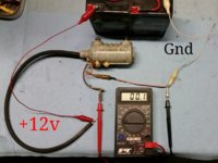
The primary lead that's connected to this ground is the common tie point, which in this case is the orange/pink wire, which goes to the points.
Now the ground wire (white here) is clipped onto the other primary lead.
The meter is showing -4.8 mv, a significant voltage.

Now, this primary lead that's connected to ground is the far side of the primary, which in this case is the brown wire, which goes to switched power.
For this test, +/- voltage on the meter doesn't matter.
We're just looking for zero volts versus some voltage.
Clear as mud?
The ground wire (white here) is clipped onto one of the primary leads.
The meter is showing 0.1 mv, practically zero.

The primary lead that's connected to this ground is the common tie point, which in this case is the orange/pink wire, which goes to the points.
Now the ground wire (white here) is clipped onto the other primary lead.
The meter is showing -4.8 mv, a significant voltage.

Now, this primary lead that's connected to ground is the far side of the primary, which in this case is the brown wire, which goes to switched power.
For this test, +/- voltage on the meter doesn't matter.
We're just looking for zero volts versus some voltage.
Clear as mud?
Last edited:
Not to be a contrarian (but I amIf ground is applied to the opposite end of the primary, current will flow thru the secondary AND the primary. A voltage will appear on the meter.
Last edited:
What he's trying to do doesn't involve the gap. He wants to see which terminal has the primary between it and the node. Then he's taking advantage of being able to measure milliamps to look for a smaller current at the one that has the primary. Unless I misunderstand what he's doing which I might be because more important things are demanding most of my attention 
Actually he's doing something craftier. Note he changes where the ground is, and if it's on the node terminal the meter will see nothing. Pretty good. Could even do it with a test light instead of a meter. On second thought it would have to be a pretty sensitive test light.... The voltage divider formula says the voltage when it's there would be pretty small.
Actually he's doing something craftier. Note he changes where the ground is, and if it's on the node terminal the meter will see nothing. Pretty good. Could even do it with a test light instead of a meter. On second thought it would have to be a pretty sensitive test light.... The voltage divider formula says the voltage when it's there would be pretty small.
Last edited:
... we're doomed....
Says it for me.
I guess we'll let this set and cook awhile.
See if it sinks in...
I fully understand what 2M is doing. What I'm saying is that in the real world..... it's irrelevant.... there is no pathway for the current to get through the secondary. Why are we measuring how much current bleeds through the secondary when we reverse polarity.... when in the real world there's a big ass air gap that stops that current dead in it's tracks?What he's trying to do doesn't involve the gap. He wants to see which terminal has the primary between it and the node. Then he's taking advantage of being able to measure milliamps to look for a smaller current at the one that has the primary. Unless I misunderstand what he's doing which I might be because more important things are demanding most of my attention
79josh81
XS650 Addict
Electrically, this conversation went way over my head about three hours ago.
If you Google "Kettering ignition", it'll show that the common tie point of the primary and secondary needs to go to the condenser, and points...
Why we are doing it...I was just taking him on his word that it's desirableWhy are we measuring how much current bleeds through the secondary when we reverse polarity.... when in the real world there's a big ass air gap that stops that current dead in it's tracks?
X-ray those single output coils!!!!!!!!!
Scott
Scott
OK.... reversing the polarity on the primary side of the coil does not..... let me repeat that... does not change the polarity on the points and the condenser. The 12v from the battery will still pass through them in the direction god intended.
The secondary is open..... let me repeat that.... the secondary is open. There is no completed circuit because the spark plug has this huge gap in it and we all know that metal has to touch metal for current to flow. We get the spark because high voltage 15-20 thousand volts says f&ck you, I don't need no stinkin' metal... I'm just gonna jump across that gap. The battery hangs it's head in shame.... .... and sez... I can't do that, I'm just a lowly 12 volts....
  .
.
The primary lets the battery voltage pass through it to the points and condenser where there is a completed electrical path for them electrons to flow.....
So..... how exactly are them lowly 12 volt electrons gonna pass through the secondary and screw this whole process up...... with that spark plug sittin' there sayin'..... "thow shall not pass?"
The secondary is open..... let me repeat that.... the secondary is open. There is no completed circuit because the spark plug has this huge gap in it and we all know that metal has to touch metal for current to flow. We get the spark because high voltage 15-20 thousand volts says f&ck you, I don't need no stinkin' metal... I'm just gonna jump across that gap. The battery hangs it's head in shame....
The primary lets the battery voltage pass through it to the points and condenser where there is a completed electrical path for them electrons to flow.....
So..... how exactly are them lowly 12 volt electrons gonna pass through the secondary and screw this whole process up...... with that spark plug sittin' there sayin'..... "thow shall not pass?"
Last edited:
... high voltage 15-20 thousand volts says f&ck you...
No kiddin'.
I've been bit numerous times.
The worst was with my 300kv experiments.
... So..... how exactly are them lowly 12 volt electrons gonna pass through the secondary and screw this whole process up...... with that spark plug sittin' there sayin'..... "thow shall not pass?"
This "Kettering ignition" stuff does gets complicated. Lotsa info out there on the net, with an awful lot of confusion and misinformation. These videos, produced by an engineering college, shows the action thru the coil, but they got the points backwards.
Here's another video showing the Kettering ignition, but they got the secondary wiring wrong, going to ground instead of internally to the primary.
I use a variety of circuit simulators. Made this one about 3 years ago, as a base for other experiments, like the LED Timing Light. It shows a lot of ancillary info, like instantaneous voltages, waveforms, current flows. Quite entertaining.
There's a lot of things happening in the ignition system during the ignition event, gets complicated, involving current, voltage, magnetic flux, capacitance, coils, transformer stuff, ...etc. Here's an attempt at breaking it down in minuscule steps.
At the beginning, the points are open, no current is flowing.
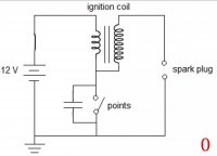
Now, the points close, and current begins to flow thru the primary.
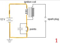
This current builds the magnetism in the core.
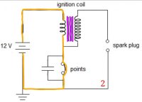
At the beginning, the points are open, no current is flowing.

Now, the points close, and current begins to flow thru the primary.

This current builds the magnetism in the core.

The core becomes saturated, fully charged with magnetism.
The points open, halting current flow to ground. The primary current is diverted to the condenser, saving the points from excessive arcing.
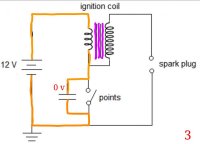
The condenser begins to charge, absorbing the inductive "freight train" of current from the primary. But, as it's charging, it's also slowing the primary's current, which begins the breakdown of magnetic flux in the core. This change in the core's magnetism induces the beginning of voltage in the secondary coil.
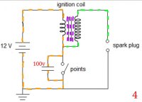
When the primary's current is halted, the core's magnetism energy is transferred to the secondary coil, enuff to initiate spark at the spark plug.
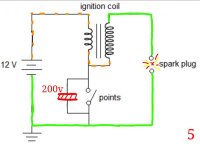
Notice that the condenser is also now fully charged, at voltages that can exceed 200v.
The points open, halting current flow to ground. The primary current is diverted to the condenser, saving the points from excessive arcing.

The condenser begins to charge, absorbing the inductive "freight train" of current from the primary. But, as it's charging, it's also slowing the primary's current, which begins the breakdown of magnetic flux in the core. This change in the core's magnetism induces the beginning of voltage in the secondary coil.

When the primary's current is halted, the core's magnetism energy is transferred to the secondary coil, enuff to initiate spark at the spark plug.

Notice that the condenser is also now fully charged, at voltages that can exceed 200v.
The condenser acts like an electrical spring. Fully charged at that high voltage, it actually causes a reverse current thru the primary, enhancing the magnetic flux change, boosting the secondary's output, maintaining the sparkplug's "burn" time.

Eventually, the condenser discharges, secondary voltages drop, the spark plug quits firing. The situation almost looks like the dormant condition at the beginning of this event.
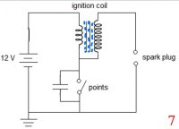
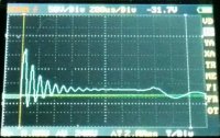
Except, there's residual reverse magnetism in the coil's core, current continues to flow backwards, the condenser absorbs this as negative voltage. That current eventually stops, and the whole thing reverses itself, going back-and-forth several times, creating the signature "Kettering ringing". If the condenser and coil primary are properly matched, the reversals can produce additional *spark* events at the sparkplug.
Here's a scope trace snapshot of my XS1B's ignition voltages, taken from the coil's negative (points) side.

Eventually, the condenser discharges, secondary voltages drop, the spark plug quits firing. The situation almost looks like the dormant condition at the beginning of this event.

Except, there's residual reverse magnetism in the coil's core, current continues to flow backwards, the condenser absorbs this as negative voltage. That current eventually stops, and the whole thing reverses itself, going back-and-forth several times, creating the signature "Kettering ringing". If the condenser and coil primary are properly matched, the reversals can produce additional *spark* events at the sparkplug.
Here's a scope trace snapshot of my XS1B's ignition voltages, taken from the coil's negative (points) side.

Last edited:
This all happens rather quickly. From my scope traces of my XS1B's ignition, the time from points opening to spark initiation is about 25 microseconds, and the Kettering ringing has a frequency of about 10khz.
Now, the coil polarity.
When you buy an ignition coil, for the traditional Kettering system, there's 2 terminals.

Which is which? Which one goes to power, which goes to the points? Look closely and you should see markings alongside the terminals, "+" and "-" on this coil.
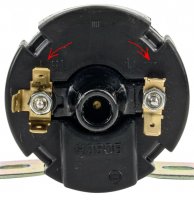
Normally, the "-" terminal, going to the points, has the shared common-tie between the primary and secondary. But, this isn't always the case. There's coil implementations out there that have this reversed.

Our ignition coils conform with the type "B" in the above pic, showing the common-tie at the (-) terminal. Although this pic shows the secondary output to be (+), it depends on the winding directions.
Now, the coil polarity.
When you buy an ignition coil, for the traditional Kettering system, there's 2 terminals.

Which is which? Which one goes to power, which goes to the points? Look closely and you should see markings alongside the terminals, "+" and "-" on this coil.

Normally, the "-" terminal, going to the points, has the shared common-tie between the primary and secondary. But, this isn't always the case. There's coil implementations out there that have this reversed.

Our ignition coils conform with the type "B" in the above pic, showing the common-tie at the (-) terminal. Although this pic shows the secondary output to be (+), it depends on the winding directions.
Last edited:
This produces a challenge, since we want negative current going to the sparkplug, as noted by PamcoPete, above. It gets complex because of the combination of construction types used in coils. Are the primary and secondary windings in-phase, or anti-phase? Are they wound right, or left-hand? Which terminal has the common-tie?
A simplified drawing of a coil's construction.

A close-up, showing the windings paralleling each other, in-phase.
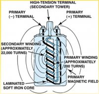
Where this gets tricky is during the reverse boost provided by the discharging condenser. In one scenario, the reversed currents of the two coils go in the same direction (desired). In the other scenario, the reversed currents go opposed, somewhat cancelling the boost effect, reducing plug voltage, creating more heat. There's a lot of recommendations out there to simply reverse the ignition coil wiring to get proper spark polarity, but these could introduce this unwanted reduction in coil performance. Some advise against it, claiming that their ignitions wouldn't spark at all.
Hopefully, the factory engineers did their homework and gave us an ignition system that gives optimal performance, and correct spark polarity. Probably should double-check this, since there's been some historical claims of the weak XS650 ignitions.
A simplified drawing of a coil's construction.

A close-up, showing the windings paralleling each other, in-phase.

Where this gets tricky is during the reverse boost provided by the discharging condenser. In one scenario, the reversed currents of the two coils go in the same direction (desired). In the other scenario, the reversed currents go opposed, somewhat cancelling the boost effect, reducing plug voltage, creating more heat. There's a lot of recommendations out there to simply reverse the ignition coil wiring to get proper spark polarity, but these could introduce this unwanted reduction in coil performance. Some advise against it, claiming that their ignitions wouldn't spark at all.
Hopefully, the factory engineers did their homework and gave us an ignition system that gives optimal performance, and correct spark polarity. Probably should double-check this, since there's been some historical claims of the weak XS650 ignitions.
Similar threads
- Replies
- 6
- Views
- 503
