Note: Yamaha has long specified that contact breaker points be set with a timing light and that is how the later service manuals describe setting points’ timing and verifying advance function. When timing lights are not available – alternative methods are sometimes employed to determine initial static timing.

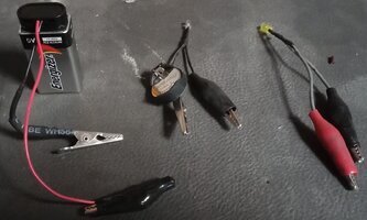
I have sensed some confusion out there in XS land regarding gadgets called “test lights”. There are, on the market today, two kinds of test lights; one tests for voltage and another tests for continuity. Both types look very similar, but with major differences – polar opposites.
The voltage tester does not have its own power supply. It is used to test “live” circuits (key on). One “lead” – typically a clip (clamp) - is hooked to ground (aka battery negative [-], the frame or engine, earth). The other lead (point) is used to find voltage in a circuit; typically, at a connector, terminal, etc. Most old-timer mechanics have this type. If you touch its two leads together, it does nothing.

The continuity tester must have its own power source, by design – usually a battery AA (AAA). It is used only to test circuits when power is off or the circuit is unhooked. It can be used to test the completeness of a wire, the function of a switch, integrity of a removed fuse. The clip is attached to one location in the circuit (or to ground if appropriate) and the point is contacted to another location to determine if they are connected (electrically). Most “home centers” sell this type. If you touch the two leads together, the light comes on (assuming good battery).

To compound the potential confusion above, either type can be used to test points (other switches) and their timing.
Voltage testers need to have the circuit powered (key on) and all the wiring hooked-up. The light will come on when the points are open.
Continuity testers must have the key off and (ideally) the points wire should be unhooked at the connection to the coil. When the points are closed, the light will come on.
Ohm meters (aka multi-meters), “buzz-boxes” are continuity testers.


I have sensed some confusion out there in XS land regarding gadgets called “test lights”. There are, on the market today, two kinds of test lights; one tests for voltage and another tests for continuity. Both types look very similar, but with major differences – polar opposites.
The voltage tester does not have its own power supply. It is used to test “live” circuits (key on). One “lead” – typically a clip (clamp) - is hooked to ground (aka battery negative [-], the frame or engine, earth). The other lead (point) is used to find voltage in a circuit; typically, at a connector, terminal, etc. Most old-timer mechanics have this type. If you touch its two leads together, it does nothing.
The continuity tester must have its own power source, by design – usually a battery AA (AAA). It is used only to test circuits when power is off or the circuit is unhooked. It can be used to test the completeness of a wire, the function of a switch, integrity of a removed fuse. The clip is attached to one location in the circuit (or to ground if appropriate) and the point is contacted to another location to determine if they are connected (electrically). Most “home centers” sell this type. If you touch the two leads together, the light comes on (assuming good battery).
To compound the potential confusion above, either type can be used to test points (other switches) and their timing.
Voltage testers need to have the circuit powered (key on) and all the wiring hooked-up. The light will come on when the points are open.
Continuity testers must have the key off and (ideally) the points wire should be unhooked at the connection to the coil. When the points are closed, the light will come on.
Ohm meters (aka multi-meters), “buzz-boxes” are continuity testers.
Last edited: