Programmable advance TCI Replacement

I have posted a page from my repair notes. I used the same curve for making my arduino TCI. I toyed with the idea of altering the curve, possibly having a different slope(instead of flat from 0 to 1900). In the end I decided to stick closely to the shop manual curve. Better to get it working first before experimenting. good luck
 

Attachments

  • tci repair note.jpeg
    tci repair note.jpeg
    96.5 KB · Views: 55
Just trying to understand the stock setup better. Is there a curve? Or does timing switch from 15 deg to 40 deg as soon as rpms go above 1,900 rpms. Does the 15 deg pickup drops out and the 40 deg pickup takes over? Or say at 2,500 rpms, are both pickups being used and a mid point advance created?
 
Well there is no literal curving. By curve I am referring to the entire RPM / degree advance trace.
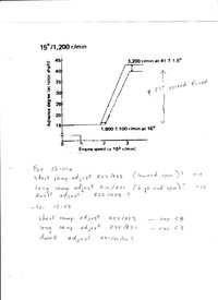
Each pickup generates an integrated waveform( ramp waveform). These wave forms are compared to determine the advance timing between the 1900 and 3300 (sloped portion of the curve). Above 3300 the comparator will switch immediately causing the top end horizontal part of the curve. At the low end (1900 rpm and lower), the long ramp wave form is reset when the second pickup pulse comes in causing the low end horizontal part of the curve. It is a simple analog computer, where the output is a variable delayed pulse inversely proportional to the rpm.
There is a misconception that the pickup pulses work independently, or one is responsible for high rpms and the other for low. This is incorrect. You need both of them for a comparison.
Think of the pickup pulses as representing the limits of travel with the old point advance system. In this analogy, the sloped part of the curve, is that area where the plate on the point system is able move and advance using centrifugal force and spring tension.
There are ways of constructing an ignitor using only one pickup. Most often these days using a microprocessor or microcontroller. If you are going to use one pickup, you would use the 1st pickup at the 40deg point. You could use the whole pickup pulse, negative and positive signals, establish an approximate rpm based on the width of the pulse, then refine your advance, by measuring the time for one complete revolution. The key is to use the first pickup pulse. The "advance" or sloped part of the curve begins immediately after this pulse. An rpm above 3300 would force you to fire right away. You could use an algorithm or a map from this point on.
 
Last edited:
Box is hard plastic with seam indicating it may come apart, but I ain't gonna endeavor a look. It is not a sealed affair peering from outside, but may well be all epoxied inside.

No documentation in envelope.

Supposed to rain tomorrow, so I may play with it - no promises:)
20220820_182826.jpg
 
Ha! Not much progress (Nascar, rabbit holes, Etc), but we have wires!
"True Kill switch" to ground installed for programming.

Pigtail TCI V11 to harness ready:
Blue - Kill Sw.
Red - R/W - 12V + (Ign circuit, coil+)
Black - B/W (jumper) - Black - pick-up (-), ground
White - Orange - coil (-)
Green - W/Gn - Pick-up 40*(+)
Yellow - Tach - NC
20220821_232137.jpg
20220821_232124.jpg

Comments, questions and "2nd set of eyes" welcome.
 
Last edited:
Looks right to me! Nicely done. Be interested to hear how easy it is to enter setup mode and access settings through Web browser. Would it be a good idea to pull your spark plugs initially and see if they fire when cranking after you set initial timing specs? :popcorn::popcorn::popcorn:
1661141975640.png
 
Thanks!
interested to hear how easy it is to enter setup mode and access settings through Web browser
Me too! :laugh2: One apprehension I currently have is this WiFI connectivity thing, blue flashing LED's (inside), modes, advancing through data fields.....yada yada. We'll see - perhaps tomorrow:shrug:

The current "rabbit hole" I'm scurrying through is this p/u location vs crank degrees- relative to spark timing. The "KC Professor", tells me not to worry about it, but I like to make things harder than they are.....

20220822_002738 (2).jpg
 
So, the first bits of setup info to be entered is "pick-up position" (attachment).
I take that to be physical position in degrees on crank rotation. Above we have the rotor magnet @ 150* (relative to TDC mark) and we have stock pickups @ 125* & 105*.
20220822_003355 (2).jpg

Based on above, I think the value it wants - for pickup position - is 45* ??
 

Attachments

  • TCI V11 SETUP PG1.pdf
    27.1 KB · Views: 69
Sounds right. I think that if it were me, I'd input 50 or 55° as a starting point. Start retarded so there's less risk of kickback.
Once you have a solid handle on the relationship of the TCI pickup to TDC, as the box see's it, adjust it using the new (verified) number?

That all make sense? :umm:
 
So, the first bits of setup info to be entered is "pick-up position" (attachment).
I take that to be physical position in degrees on crank rotation.
I think they mean when the pick-up is triggered.
If the pick-up is triggered at 15 deg before tdc then 15 is what is used.
 
You referencing Appendix 1 in the setup guide? Has two examples. I think GLJ is correct. Looking for the position of pickup BTDC.
1661174457545.png
 
Back
Top