Who Knows Something About the Gear Selector Mechanism?

abyssmaltailgate

Greenhorn Mechanic
Messages
148
Reaction score
8
Points
18
Location
Chicago
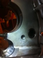
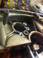
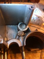
I think I might've lost the "plug" (Haynes, pg. 35, part #17). Although the pictures in the manual suggest otherwise, can anyone tell me if this is how the "selector fork shaft" is supposed to sit or is it clearly missing the plug? Seems like it's in too far and needs the plug to sit properly. Should there be some play? I mean, this assembly does contain several other moving components. Or is the plug "glued" place? The casting opposite where the "selector fork shaft" and "plug" sits does look like something might have been frozen in place (both top engine case halves I have look like this).
2016-08-01 16.41.53.jpg
Unfortunately, the Yamaha parts house seems to no longer carry them. Here's the link to that reference:

http://www.yamahapartshouse.com/oemparts/p/yamaha/90334-10007-00/plug-straight-256-15439-00

Lastly, does anybody have any idea where I might be able to find a replacement (other than a parts bike) or figure out what I could do or use to put in there so it sits correctly?
 

Attachments

  • 2016-08-01 16.40.53.jpg
    2016-08-01 16.40.53.jpg
    131.5 KB · Views: 358
  • 2016-08-01 16.41.17.jpg
    2016-08-01 16.41.17.jpg
    154.5 KB · Views: 349
  • 2016-08-01 18.02.06.jpg
    2016-08-01 18.02.06.jpg
    149.3 KB · Views: 335
Good to know, just bought both of them like a spazz, but can anyone confirm how the selector fork shaft should sit? Should it be recessed or protruding? Thanks!
 
Thanks for the link 2M, but unfortunately, it's not quite what I'm looking for. Let me try explaining it another way. Pull out your Haynes manuals for this one; you're gonna need it...

When assembling the gear selector mechanism, the "selector fork shaft" runs through the bottom of all 3 "gear selector forks" and finally sits in a recess on the inner left side of the upper crankcase. This recess is found below another, larger recess which comprises the "needle roller bearing" where the gear selector drum" sits and articulates. The one I am concerned with is the smaller of the two machined, circular recesses. On the outer left side of the upper crankcase, the opposite sides of both recesses can be observed. The smaller one, to which I am referring, has an irregularly shaped casting mark or filler on it (you can see this in the 3rd picture of my first post).

The Haynes manual displays a small piece called the "plug" that sits at the end of the "selector fork shaft" (Haynes, pg. 35). This "plug," allegedly, sits in the recess described above; however, I am unable to tell if the plug actually sits in that recess or if it is already casted or molded into the case. Relative to the case, the "selector fork shaft" DOES NOT sit flush with the outer right side of the upper crank case when it is situated in the appropriate recess. Pictures in several manuals and forum posts indicate the right most edge of the "selector fork shaft" SHOULD sit flush or even protrude when reassembling in order to articulate with the "selector pin" and "gear selector claw"; however, none of these tutorials explain whether or not there is play in the recess so the "selector fork shaft" would need to be lifted and held in place for fitting upon reassembly.

When disassembling the gear selector mechanism, I didn't notice the "plug" fall out, but it seems to be a very small piece that is easily lost. Additionally, its name suggests it is used to plug or fill a hole, possibly one that was made or left when casting the cases. Based on my suspicions, I reckon this COULD be why every XS650 engine case has those strange surfaces on the outside of the upper casting on the left. Again, nothing speaks to the contrary. As mentioned, this mechanism contains many moving parts so it is possible that it needs extra lateral play, which is why there is so much room in the recess.

Even though I have yet to see this "plug" pictured in any assembly or disassembly walk throughs, forum posts, or even in the manuals (besides exploded drawings), I also have yet to see anything that says the plug is casted into the case.

Beers are on me to whoever has the answer to this and can show me or explain how this mechanism is correctly reassembled.
 
Okay, let's give 'er a go thisaway. The holes for the shiftfork guidebar were line-drilled completely through both sides of the case upper. There's an oil delivery gallery that enters the side of the left-side hole.

So, that hole needs to be plugged, using that plug, part #17 below, along with some magic sealing goo, which was already done at the factory. Consider it now as a permanent part of the case (unless you drove it out). Numerous oil galleries exist in the case and right sidecover that are drilled and plugged thataway. There needs to be some space between that plug and the end of the hollow guidebar, so that oil can enter the guidebar.

Now, the guidebar has oiling holes that need to be in a certain place, and it must not be allowed to slip too deep into that left case hole, else it could block oil delivery. To retain the guidebar at its proper position, it has a notch in its right side, into which the end of the 'C' shaped stopper is fitted, as noted above in Airwolfie's post #6.

To help visualize this, hold onto yer panties for a torrent of pictures.

An excerpt from the 1976 parts manual, showing the guidebar #16, case plug #17, and 'C' shaped stopper #24.

76-XS650C-Shifter1-01.jpg
76-XS650C-Shifter1-02.jpg
 
Last edited:
Here's where it gets fun. (Many thanx to YAM277, gggGary, and others for these pics)

There's a secret/hidden passage that delivers oil to the bearing area behind the clutch pushrod oilseal.

HiddenGallery.jpg
SecretPassage76.jpg
SecretPassage79-02.jpg


This shows the oil flow to the mainshaft roller bearing, then onward to the guidebar.

SecretPassage79-01.jpg


It seems that, possibly starting in 1980, the 'secret' passage became a visible canal.
The other red line/arrow shows the oil delivery gallery to the guidebar.

XS650-GuideBarOiling80.jpg
 
Last edited:
So, the bottom line is: If you haven't disturbed or punched-out that case plug #17, there's no need to worry about it.

Looking at your last pic in post #1, it appears that the plug is still there where it's supposed to be. Looks like sandblasting may have roughed-up the sealer. Probably not an issue. But, if you want the extra security, I suppose you could smear a little sealer or jb-weld over that.

You should clean/flush all those galleries, ensure they're clear. Also, you could slide the guidebar fully into that hole, making sure that it must be withdrawn about 1/8", for its notch to be captured by the 'C' shaped stopper (per Airwolfie's post). That would confirm that oil can enter the guidebar from that end.

Clear as mud???
 
Last edited:
Clear. As. Mud. Thanks 2M! This exactly what I was looking for and confirms my suspicions. Wish we didn't have to go to such a great length to arrive at this conclusion.

The only question I have left is "whadya drink?" :bow2:
 
Haha, seems that my current 'thing' is anything with a Starbucks label.

Actually, I'm glad you brought this up, as it was a kind of research item a few months ago...
 
Back
Top