XS1 Build

oh did I make another drunken and over expressive post? hah I meant no offence to anyones.

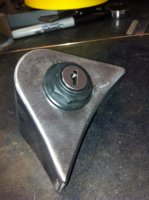
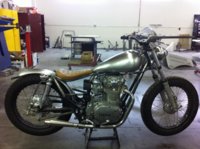
comin' on nicely. this 3/4 pinch is roundabout the top shock mount? I think so... lines flow nice into there on the last pic.
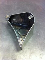
neck gusset looks unusual... finished or have you further plans there? :thumbsup:

Ah, I'm not one to hold a grudge, lol.

Thanks. yeah, the bend is further down on the tube, but narrowed about 1.5" total at the upper shock mounts.

The neck gusset is weird, I know. I made it that way so the bottom flows with the tank and the top is cutout to give me access to brackets under the top tube. It doesn't look so odd with the tank on.
 
nice work there..i like it.I'm really diggin' the 36 3 window in the background..yours? i've got a 5 window project of my own goin' on..keep up the good work..i have a friend that owns V.C.T.,( Vintage Chevy Trucks) in your area..i was last there in '87...
 
Thanks drog. No, unfortunately the 36 doesn't belong to me, it's a customers car. Hmm, I haven't heard of VCT, I'm still kinda new to the area...
 
The carbs were a little crusty and needed some attention. One of the bowls was cracked and someone had jb welded it. I swapped out the bowl and a couple other parts off another set I found. Got some new jets to play with too!

IMG_0917.jpg

IMG_0918.jpg

IMG_0920.jpg

Ready for assembly!

IMG_0922.jpg
 
How are the throttle shafts in the bores? Especially the side the cable attaches to.
 
Did you check the needle-jet/emulsion-tube fit, it's o-ring, and emulsion holes?

All I really did was check to make sure there were no obstructions, but i didn't remove it. I guess the carbs being as old as they are that o-ring probably isn't good? Those tubes are just pressed in? How hard is it to get em out? I was a bit worried about damaging them...
 
All I really did was check to make sure there were no obstructions, but i didn't remove it. I guess the carbs being as old as they are that o-ring probably isn't good? Those tubes are just pressed in? How hard is it to get em out? I was a bit worried about damaging them...

Yeah, judgement call here. If it is fully seated and feels solid, might just let it be. It just pulls out, held in by the o-ring, but can be a bear to get it out, depending on corrosion/crud. Aggressive removal could damage it. That tiny 1.0 x 4.0mm o-ring, part #3 in the attached list, can be hard to find...
 

Attachments

  • Carb-XS1B.jpg
    Carb-XS1B.jpg
    263.1 KB · Views: 164
  • XS650-Carb-Orings.jpg
    XS650-Carb-Orings.jpg
    113.8 KB · Views: 134
Nothing inside looked that bad and the only real corrosion was on the chrome. So, the tube is not a press fit in the carb body? it's actually wedged by the o-ring? I thought maybe the o-ring just seated between the flange/step of the tube and the carb. I replaced one of the barbs on the side of the carb and it was pressed in, not the case here?

And yeah, not being able to source parts was a concern of mine :(
 
Ok, I see now. There's a little groove for the o-ring, it was hard to see in the diagram... I read the thread you linked me to, thanks. I'll check out the emulsion tubes again and make a call.
 
Here's a video of me starting her up for the first time... it's old, I have since rebuilt the engine and carbs. I'm trying to play catch up with my thread. Sorry, some things aren't exactly in chronological order and not very thorough, but hey! it's my first time! :D

 
Its been quite a while since the last update... I've got it on the road, but am still working out some of the details. I'll do a little recap to show the progress.

Here is the beginning of the seat. I made the pan out of some 16ga mild steel, the wood part is just some 3/8" plywood that will be used to staple to once the cover is put on. After cutting out the plywood border, I soaked it in warm water and clamped it to the pan to give it the same shape. I later sealed the wood with some urethane. I welded some 1/4" studs to the pan and mounted the brackets to be tacked onto the frame.
 

Attachments

  • IMG_0945.jpg
    IMG_0945.jpg
    242.6 KB · Views: 166
  • IMG_0950.jpg
    IMG_0950.jpg
    255.3 KB · Views: 153
Got the seat brackets tacked on, painted the pan and took it over to a local upholstery shop to have the cushion and cover made. Pretty happy with the results!
 

Attachments

  • IMG_1218.jpg
    IMG_1218.jpg
    194.1 KB · Views: 140
  • IMG_1219.jpg
    IMG_1219.jpg
    221.8 KB · Views: 157
  • IMG_0962.jpg
    IMG_0962.jpg
    236.5 KB · Views: 172
Made this little box for the ignition switch to tuck underneath the seat right against the back bone.
 

Attachments

  • IMG_1019.jpg
    IMG_1019.jpg
    253.2 KB · Views: 181
  • IMG_1212.jpg
    IMG_1212.jpg
    226.8 KB · Views: 164
  • IMG_1211.jpg
    IMG_1211.jpg
    174.6 KB · Views: 150
  • IMG_1210.jpg
    IMG_1210.jpg
    238.4 KB · Views: 160
  • IMG_1017.jpg
    IMG_1017.jpg
    249.5 KB · Views: 166
Made a little fuse box to hide under the swing arm against the frame...
 

Attachments

  • IMG_1213.jpg
    IMG_1213.jpg
    215 KB · Views: 158
  • IMG_1214.jpg
    IMG_1214.jpg
    229.1 KB · Views: 171
I didn't have enough space under the new tank for stock coils, so I was trying to figure out where to put em. I came up with this enclosure for the coils and condenser. It attached to the rear motor mount just above the swing arm. Unfortunately I scrapped it cause I went with an electronic ignition.
 

Attachments

  • IMG_1216.jpg
    IMG_1216.jpg
    164.7 KB · Views: 144
  • IMG_1215.jpg
    IMG_1215.jpg
    176.2 KB · Views: 159
Here's what it looked like after I put it all together. Still missing a few things...
 

Attachments

  • IMG_0958.jpg
    IMG_0958.jpg
    242.5 KB · Views: 190
  • IMG_0960.jpg
    IMG_0960.jpg
    254.9 KB · Views: 174
  • IMG_0961.jpg
    IMG_0961.jpg
    224.7 KB · Views: 170
  • IMG_1022.jpg
    IMG_1022.jpg
    240.9 KB · Views: 182
Back
Top