700cc kit with a Shell #1 cam in a 78XS650E

The A/F mixture was measured by inserting the sensor tube through the hole in the center of the commando silencer baffle. The tube was long enough to reach the middle or so of the head pipe. Gary can you point me to the discussion on exhaust design you are referencing?
Here's a start.
https://www.xs650.com/threads/650-centrals-exhaust-port-optimizers-and-torque-peak-optimizers.25438/
Don't bump into the rabbits on the way down. :unsure:
My 750 currently has the exhaust port optimizers at the port end of the pipe. I didn't notice a difference on the seat pant dyno.
650 central vs mike's optimizer construction is majorly different.
It's been a while since I looked into any of this but your smaller pipe is better thesis does seem to resonate, (sorry, I'll let myself out)
 
Last edited:
Here's a start.
https://www.xs650.com/threads/650-centrals-exhaust-port-optimizers-and-torque-peak-optimizers.25438/
Don't bump into the rabbits on the way down. :unsure:
My 750 currently has the exhaust port optimisers at the port end of hte pipe. I didn't notice a difference on the seat pant dyno.
650 central vs mike's optimisers construction is majorly different.
It's been a while since I looked into any of this but your smaller pipe is better thesis does seem to resonate, (sorry, I'll let myself out)
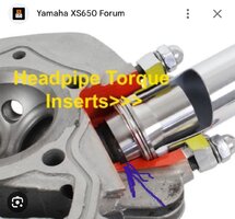
MMM and mikesXS/heiden tuning indeed have very different exhaust port optimizer designs. One thing that MMM pointed out is that in the diagram below the gasket is on the wrong side of the optimizer flange creating a gap shown with the purple arrow.
 

Attachments

  • IMG_4722.jpeg
    IMG_4722.jpeg
    167.1 KB · Views: 50
MMM and mikesXS/heiden tuning indeed have very different exhaust port optimizer designs. One thing that MMM pointed out is that in the diagram below the gasket is on the wrong side of the optimizer flange creating a gap shown with the purple arrow.
Post the diagram/pic please. I have optimizers for my 1.75 pipes on the tracker (thanks @Ben1) and the pipes are off at this point so I can do a dry run.
 
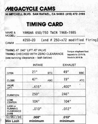
Do you have the specs on the shell #1 cam? Attached are the specs for my cam.
 

Attachments

  • Megacycle Cam Timing Card.jpg
    Megacycle Cam Timing Card.jpg
    165.2 KB · Views: 32
This head pipe discussion is definitely interesting. It seems the consensus is that 38 mm OD/ 35 mm ID is a good size for most XS engine configurations. Other, higher performing/ larger displacement twins actually have smaller headpipes. Norton Commando 850 had 35 mm OD, modern BMW 800/900 parallell twins also have quite small headers, just like the 700 cc Yamaha CP engine in the XSR/MT/Tracer/ Tenere. And at least these modern 4 valve engines surely have camshafts with shorter duration than the XS. Definitely something to ponder....
 
Did you need to shorten the valve guides with that cam? Even with low profile valve seals I had zero clearance on the intakes before cutting them down.
 
Did you need to shorten the valve guides with that cam? Even with low profile valve seals I had zero clearance on the intakes before cutting them down.
no shortening of the valve guides was needed, but I did not work on the head myself, sent it to Roger at R&D
 
One important point, I am running valve clearance per Hoos: intake 0.006" and exhaust 0.008". Have not tried 0.012" exhaust recommended by Shell. Gary says the reason for the lower recommended clearance is to take it easier on the valve train, which i appreciate. The lower clearance should incease the valve overlap and the timing of the exhaust though.
 
Last edited:
This head pipe discussion is definitely interesting. It seems the consensus is that 38 mm OD/ 35 mm ID is a good size for most XS engine configurations. Other, higher performing/ larger displacement twins actually have smaller headpipes. Norton Commando 850 had 35 mm OD, modern BMW 800/900 parallell twins also have quite small headers, just like the 700 cc Yamaha CP engine in the XSR/MT/Tracer/ Tenere. And at least these modern 4 valve engines surely have camshafts with shorter duration than the XS. Definitely something to ponder....
after some discussions with MMM, I will be fitting his TPO inserts with OD 1 3/8" (1 1/4 ID) to the 1 3/4" headers I tried. Will report in a few months.
 
Last edited:
here is a nice view of valve lift for the the Shell #1. since the megacycle lobe centers are at 104 degrees, I would think that there is less valve overlap assuming the rest of the grind is similar. So more torque, less top end? just guessing here https://www.xs650.com/threads/anybody-recognize-this-cam.38585/post-642060
I think that makes sense. As compared to my stock motor the modified one has quite a bit more midrange torque. With the stock motor I consistantly found myself running it to higher rpms before shifting.
 
here is a nice view of valve lift for the the Shell #1. since the megacycle lobe centers are at 104 degrees, I would think that there is less valve overlap assuming the rest of the grind is similar. So more torque, less top end? just guessing here https://www.xs650.com/threads/anybody-recognize-this-cam.38585/post-642060
here is a very good link showing how to time a cam as well as mentioning impact of valve overlap:

https://www.thumpertalk.com/blogs/entry/227-checking-and-setting-cam-timing/

"...As a rule of thumb, reducing the lobe separation angle by advancing the intake and retarding the exhaust camshaft will increase valve overlap, move power further up the power curve, increase cylinder pressure, increase the chance of detonation, and reduce the piston to valve clearances. On the contrary, increasing the lobe separation angle by retarding the intake cam and advancing the exhaust cam will have somewhat of the opposite effect. There will be less valve overlap, power will move to a lower RPM, chances of detonation will be reduced, and the valve to piston clearances will increase."
 
Back
Top