Inductive Kickback of alternator rotors
Back in the `60-70s, as alternators replaced generators, and semiconductor electronics started appearing in automobiles, an electronics phenomen started causing problems for the automakers, Inductive Kickback. Essentially what happens is that current flow through an inductive device (like the alternator rotor) doesn't instantly stop when a circuit is switched off. The current will want to continue flowing like a freight train with bad brakes. What happens then is the now-disconnected positive supply line voltage will momentarily go below ground voltage, seen as a negative voltage spike on a scope. Inductive kickback spikes could be seen on some of those earlier cars on the order of hundreds of volts, but since they were point/coil ignitions with relay type regulators and vacuum-tube radios, nobody got hurt, except for the occasional backfire.
Enter the Yamaha XS-650, with it's large inductive rotor. The rotor is still trying to pull current when the ignition is shut off, and the brown ignition supply line is now isolated from the battery, and floating, subject to the inductive kickback of the rotor, and will spike to negative voltages. On the older relay type regulators, the other side of the rotor is grounded, and will drain there. On a semiconductor regulator, the green grounding line will spike 'high', stressing the regulator. With a points/coil system, if one of the points happens to be closed, most of that will be drained through a coil, possibly causing a backfire through a carburetor.
The early models, with point/coil ignitions and relay type regulators produce a lot of line noise, but with no semiconductor devices, were essentially immune to this and ran fine.
Fast forward to the later models with their solid-state regulators and ignitions, and you can see a potential problem. Typical nonprotected semiconductor devices of the period were damaged when exposed to inverted voltages of 5v or more. Well designed electronics included some sort of protection. Modern semiconductor devices typically have diode-protected inputs built-in.
The volume of posts about failed TCI's and regulators lead me to think that the aging, well-used, heat-cycled protection diodes in those devices appear to be failing, leading to the cascade of failures deeper inside the contraption. And the plethora of cost-reduced and quality challenged electronics available to the bike maintainer adds to this issue. Also, spikes could occur with bouncing brushes, and unusual methods of grounding the rotor's green line.
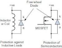
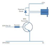
Standard electronics design involving inductive devices includes the use of a diode to shunt this inductive kickback back into the inductor, and are known as protection diodes, freewheel diodes, flywheel diodes, ...etc. This removes most of the negative spike from the supply line, and protects all devices on that line. View these attachments for typical implementations of Inductive Kickback Protection Diodes. For more info, Google "inductive kickback", "protection diode", "flywheel diode" and "freewheel diode".


An excellent example of this kickback was observed by member fiveohindc, who inadvertently attached a neutral light "LED" backwards, noting a momentary glow when ignition was shut off:
http://www.xs650.com/forum/showthread.php?t=26974
How often do you hear, when the rider of a later model shuts off ignition, then later it fails to restart. This could be caused by this 'inductive kickback', and the damage could be permanent.
Back in the `60-70s, as alternators replaced generators, and semiconductor electronics started appearing in automobiles, an electronics phenomen started causing problems for the automakers, Inductive Kickback. Essentially what happens is that current flow through an inductive device (like the alternator rotor) doesn't instantly stop when a circuit is switched off. The current will want to continue flowing like a freight train with bad brakes. What happens then is the now-disconnected positive supply line voltage will momentarily go below ground voltage, seen as a negative voltage spike on a scope. Inductive kickback spikes could be seen on some of those earlier cars on the order of hundreds of volts, but since they were point/coil ignitions with relay type regulators and vacuum-tube radios, nobody got hurt, except for the occasional backfire.
Enter the Yamaha XS-650, with it's large inductive rotor. The rotor is still trying to pull current when the ignition is shut off, and the brown ignition supply line is now isolated from the battery, and floating, subject to the inductive kickback of the rotor, and will spike to negative voltages. On the older relay type regulators, the other side of the rotor is grounded, and will drain there. On a semiconductor regulator, the green grounding line will spike 'high', stressing the regulator. With a points/coil system, if one of the points happens to be closed, most of that will be drained through a coil, possibly causing a backfire through a carburetor.
The early models, with point/coil ignitions and relay type regulators produce a lot of line noise, but with no semiconductor devices, were essentially immune to this and ran fine.
Fast forward to the later models with their solid-state regulators and ignitions, and you can see a potential problem. Typical nonprotected semiconductor devices of the period were damaged when exposed to inverted voltages of 5v or more. Well designed electronics included some sort of protection. Modern semiconductor devices typically have diode-protected inputs built-in.
The volume of posts about failed TCI's and regulators lead me to think that the aging, well-used, heat-cycled protection diodes in those devices appear to be failing, leading to the cascade of failures deeper inside the contraption. And the plethora of cost-reduced and quality challenged electronics available to the bike maintainer adds to this issue. Also, spikes could occur with bouncing brushes, and unusual methods of grounding the rotor's green line.
Standard electronics design involving inductive devices includes the use of a diode to shunt this inductive kickback back into the inductor, and are known as protection diodes, freewheel diodes, flywheel diodes, ...etc. This removes most of the negative spike from the supply line, and protects all devices on that line. View these attachments for typical implementations of Inductive Kickback Protection Diodes. For more info, Google "inductive kickback", "protection diode", "flywheel diode" and "freewheel diode".


An excellent example of this kickback was observed by member fiveohindc, who inadvertently attached a neutral light "LED" backwards, noting a momentary glow when ignition was shut off:
http://www.xs650.com/forum/showthread.php?t=26974
How often do you hear, when the rider of a later model shuts off ignition, then later it fails to restart. This could be caused by this 'inductive kickback', and the damage could be permanent.


