Hi all,
I've got an '82 xs650 that I've been modifying for awhile. I'm finally at the part of the build I dreaded all along -- wiring. I'm ashamed to say that I know ZERO about wiring.
I'm looking at running a super simple setup with only the basics. Headlight, taillight, kick start, speedo (does that require power?). I've already done a fair amount of researching (this thread is great: http://www.xs650.com/forum/showthread.php?t=61), but I'm still not sure which diagram suits my needs. I know everyone says to use what you need and disregard the rest, but I was wondering if anyone had a wiring diagram that fit exactly what I'm going for.
Thanks in advance for any help.
EDIT: I have no idea whay the thread title says 'setuphio.' I don't know how to edit it out either.
Last edited:

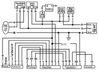


 the yellow is capped off TO eliminate the safety switch the key switch is a simple on/off since the circuit uses a starter button, here it is drawn out like what you are saying you want, after eliminating the safety switch the blue white wire from the start button goes direct to the starter solenoid but if you keep the E-start it only makes sense to keep the starter safety switch, if you go kick only the start button and solenoid/starter motor goes away
")