Hold up. My brain just stopped. Wiring fault.

jasidok

Live Life to the fullest!
Messages
93
Reaction score
81
Points
18
Location
Denver, CO
A0F2D69B-A76C-4B77-8BFE-1B5C6A01978F.gif
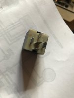
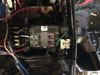
Ok I need to get another pair of eyes on this. I’ve rewired my whole bike to this schematic. Well, mostly so far. So, there’s this whole “main relay” thing. But I’m not using a safety relay and there’s only 4 hook ups to the “MR” on the schematic. So I figure it’s just a universal thingy from auto zone. Check. Picked it up went to hook it up.... when now hold on a minute here... is that just a weird loop after the MR to the ignition switch? Wait... am I reading this weird? Does the way that the schematic currently show kind of make the whole ignition switch completely pointless? The main relay is connected to both the main battery positive wire and the 5a fuse that comes from the Ignition switch..... whoa.... my head hurts. Someone help me out here....


and while we’re here... my REG/rec came with a Pma kit from MikesXS With the e advancer and pamco. Ok. So... my reg/rec from mikes only has the red and green leaving it. There’s only 5 wires. Not 6. Is that ok? Everything is all good right? I just don’t connect the 6th wire to the wiring harness. Just one to ground. one to battery. The end. And that’s all good still though, yes?
 

Attachments

  • image.jpg
    image.jpg
    85.3 KB · Views: 110
  • image.jpg
    image.jpg
    174.8 KB · Views: 85
Yeah, I'm not a fan of cluttered schematics, with many unneedlessly crossing lines. Adds to the confusion. I'd like to be able to redraw many of them.

Maybe it would help to visualize the guts of the master relay.
JasidocSchema.jpg


Don't know about your 5-wire rec/reg. Probably needs to be grounded at its case mount. Shortening its grounding wire, as shown, gives a better indication of case grounding...
 
Power comes from the battery on a red wire, at the junction above the M/R power flows to the 5 amp fuse and the relay. In TM's diagram you can see the relay contacts are open, no power out on the brown wire.
After the 5 amp fuse power flows to the key switch. When you turn the switch to "ON" power flows to the relay, which energizes the relay and closes the contacts, this allows the power to flow out of the relay to the rest of the bike.
This lets you use a key switch that can carry just a small amount of current, enough the reliably carry the current to trip the relay. The relay can carry the main current draw of the rest of the bike.
Leo
 
I kinda think a relay is overkill for a small motorcycle, maybe useful on some touring barge with 25 electrical accessories, Even less needed if the iggy switch is close to the fuse box....(short wire runs) What I did on madness.
 
I added a relay just to power the ignition. Power from fuse box to relay, from relay to ignition. Kill switch just trips the relay.
Wiring tis way bypasses a lot of switches and connections between the battery and ignition.
A dirty kill switch might cause ignition trouble but it can carry enough current to trip a relay.
Leo
 
There re so many wrong diagrams in the Diagram thread its not funny........Trying to sort out th mess and correcting them is a wast of time. The 2 Simplified diagrams in post #1 is a starting point................The fuse block can be installed where the 20amp fuse is and the rest removed.............Use the last diagram for the installation of the starter solenoid and indicators are simple to connect up

http://www.xs650.com/threads/some-wiring-diagrams.61/

Doing a full continuity test through a loom helps to get the head around the difference between the diagrams and the actual layout on the bike.........I had the same problem trying to get my head around the difference between the bike loom and the diagram...........just didn't compute. Once i had done the full continuity test, (still took a while), i finally related the 2..........

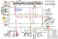
Another way is to brake down the diagrams into circuits.........
75_76_XS650 B&C Wiring copy.jpg
 
I kinda think a relay is overkill for a small motorcycle, maybe useful on some touring barge with 25 electrical accessories, Even less needed if the iggy switch is close to the fuse box....(short wire runs) What I did on madness.
I agree with that Gary... it's not like we're trying to power a toaster oven through the iggy switch
On the other hand.... I like the idea of powering the ignition through one. Only one set of contacts to worry about. Think I'll add that little mod to my next bike.
 
.
Maybe it would help to visualize the guts of the master relay.
View attachment 127056

Don't know about your 5-wire rec/reg. Probably needs to be grounded at its case mount. Shortening its grounding wire, as shown, gives a better indication of case grounding...

Ok I completely agree and this makes a lot of sense. I’ve been trying to just let it go and breathe! I think I’m overthinking it.


Power comes from the battery on a red wire, at the junction above the M/R power flows to the 5 amp fuse and the relay. In TM's diagram you can see the relay contacts are open, no power out on the brown wire.
After the 5 amp fuse power flows to the key switch. When you turn the switch to "ON" power flows to the relay, which energizes the relay and closes the contacts, this allows the power to flow out of the relay to the rest of the bike.
This lets you use a key switch that can carry just a small amount of current, enough the reliably carry the current to trip the relay. The relay can carry the main current draw of the rest of the bike.
Leo

Oooooooooooooo I get it now. Ok see now the whole thing makes sense. And even if I have an OEM ignition switch it still feels smarter.

I added a relay just to power the ignition. Power from fuse box to relay, from relay to ignition. Kill switch just trips the relay.
Wiring tis way bypasses a lot of switches and connections between the battery and ignition.
A dirty kill switch might cause ignition trouble but it can carry enough current to trip a relay.
Leo

Yea. Ok got it.
 
There re so many wrong diagrams in the Diagram thread its not funny........Trying to sort out th mess and correcting them is a wast of time. The 2 Simplified diagrams in post #1 is a starting point................The fuse block can be installed where the 20amp fuse is and the rest removed.............Use the last diagram for the installation of the starter solenoid and indicators are simple to connect up

http://www.xs650.com/threads/some-wiring-diagrams.61/

Doing a full continuity test through a loom helps to get the head around the difference between the diagrams and the actual layout on the bike.........I had the same problem trying to get my head around the difference between the bike loom and the diagram...........just didn't compute. Once i had done the full continuity test, (still took a while), i finally related the 2..........

Another way is to brake down the diagrams into circuits.........
View attachment 127083

That’s how I’m going to finish this. Breaking it down into smaller groups. I’m going to focus and the mechanics first. Starting and turning over and such. Then The head and tail lights. Then the signal flashers. Then the gauges.
 
Back
Top