-
Enjoy XS650.com? Consider making a donation to help support the site.
XS650.com receives a small share of sales from some links on this page, but direct donations have a much greater impact on keeping this site going.
You are using an out of date browser. It may not display this or other websites correctly.
You should upgrade or use an alternative browser.
You should upgrade or use an alternative browser.
Stuff my dog says; on second thought I'll just build a race car
- Thread starter NashGTI
- Start date
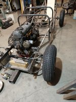
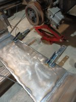
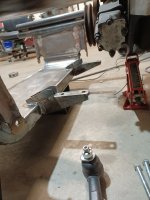
Lot's of pictures today. Started by getting the tie rod ends fitted to the spindles. Being a tapered fit stud I needed to add a couple of shims top and bottom of the plate to add thickness for the taper to seat correctly. They were located where they are trying to get the ball joint and tie rod heights equal to get the steering geometry to line up.
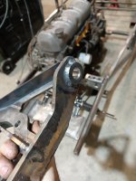
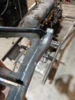
With that taken care of I got the steering rack mounts measured and welded and then went ahead and bolted on the rack.
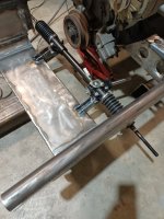
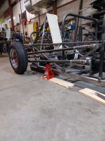
Then took a largely pointless picture with the assembled spindle hooked to the tie rod. It kind of shows wheel to frame spacing, so we can pretend that's why it happened. Mostly it's a cool look.

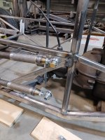
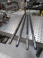
Really need the one inch die to show up for the tubing bender so I can make the control arms. Hasn't happened yet though so moved on to the rear axle and welded the four link mounts to the axle tubes.
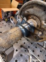
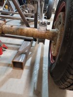
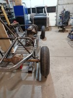
At that point I was looking at front anchor points for the four link but didn't do anymore actual work. Through the week I've been thinking about the four link in the back and specifically the Watts Link arrangement. Looking at what happens when you vertically offset the pivot point of the Watts Link. If you lift the pivot point up above the center line of the axle it will slide the axle side to side when the axle articulates. If you lift it to the point of the top of the tires it would essentially self correct the distance between the tire and body, so if you have a situation with little tire to fender clearance that would keep the tires from rubbing.
Not having fenders, and there being more than 6 inches between the tire and body I'm not really worried about body clearance with this project. The interesting thing with relevance to this though is that if you triangulate the four link bars, and side to side movement in the rear axle turns into rear steering. More stuff, like the bump steer in the front end, that would be super undesirable for a street car because pot holes would cause this and it would turn weird. As a track car though, passive rear steer appeals to me. It will be slight because of the geometry of those four link bars, but it will be there and the idea I'm thinking is worth it. I had worked all the numbers out the other morning and don't remember exactly but at full tilt it's less than a couple degrees.


With that taken care of I got the steering rack mounts measured and welded and then went ahead and bolted on the rack.


Then took a largely pointless picture with the assembled spindle hooked to the tie rod. It kind of shows wheel to frame spacing, so we can pretend that's why it happened. Mostly it's a cool look.
Really need the one inch die to show up for the tubing bender so I can make the control arms. Hasn't happened yet though so moved on to the rear axle and welded the four link mounts to the axle tubes.


At that point I was looking at front anchor points for the four link but didn't do anymore actual work. Through the week I've been thinking about the four link in the back and specifically the Watts Link arrangement. Looking at what happens when you vertically offset the pivot point of the Watts Link. If you lift the pivot point up above the center line of the axle it will slide the axle side to side when the axle articulates. If you lift it to the point of the top of the tires it would essentially self correct the distance between the tire and body, so if you have a situation with little tire to fender clearance that would keep the tires from rubbing.
Not having fenders, and there being more than 6 inches between the tire and body I'm not really worried about body clearance with this project. The interesting thing with relevance to this though is that if you triangulate the four link bars, and side to side movement in the rear axle turns into rear steering. More stuff, like the bump steer in the front end, that would be super undesirable for a street car because pot holes would cause this and it would turn weird. As a track car though, passive rear steer appeals to me. It will be slight because of the geometry of those four link bars, but it will be there and the idea I'm thinking is worth it. I had worked all the numbers out the other morning and don't remember exactly but at full tilt it's less than a couple degrees.
Oh, we were looking at blower drive and think we came up with a plan there too that involves an old power steering pulley and results in (slightly) more boost and power than I had earlier planned. With any luck we will get some outside consulting/help with that and no for certain.
Thinking about rear axle things today, the inside edge of the rear tires is six inches from the outside edge of the frame. The spring for the shock will take up 2.5 or 3 inches of that space, so call it 3. That will leave three inches to cant the shock at absolute maximum which works out to a much slighter angle than I really want. The inclination of the spring adding anti-roll to the suspension.
My thinking previously was to abandon the shock angle and mount them what is essentially straight vertical. Maybe even inboard to salvage something with the idea that if you hide the shocks inside the bodywork on an open tire rear axle it'd be kind of cool looking. Today though I realized what should have been obvious all along, the answer is to pushrod the rear coil overs
My thinking previously was to abandon the shock angle and mount them what is essentially straight vertical. Maybe even inboard to salvage something with the idea that if you hide the shocks inside the bodywork on an open tire rear axle it'd be kind of cool looking. Today though I realized what should have been obvious all along, the answer is to pushrod the rear coil overs
OK then, got a late start yesterday morning owing to the weather again. For those as yet unaware the middle of the United States had a big tornado outbreak again late Friday early Saturday morning with several killed across the area. Everyone I know is OK but several people had near misses again I avoided the area for obvious reasons but there was damage reported about a half mile south of the house this time and it sent the family scurrying for the basement about 3:30 Saturday morning. Spent a while making sure everyone close was safe and then went in and got to work.
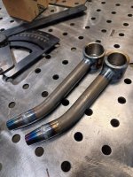
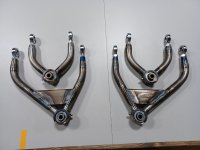
Immediately started on the control arms because I was (am) excited to see arms on the car. New bender worked like a charm and things basically worked as planned with it. The lowers bent and tacked together we test fit them to try and check for interference issues under steering. Took two people obviously with no upper arms at that time and done up found that the way the leading edge of the lower arm is done there was tire interference to the lower arms. Then it was lunch time. I'm not sure how that happened, honestly I was just working and it felt like I had only been there 45 minutes or so but it had been nearly three hours.
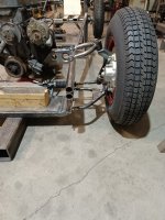
I had designed in 41 degrees of steering...on something. The 41 number I remember but I can't recall if that was inside tire, outside tire, or an average. What I've got here before the tire touches the control arm is 35 degrees on that outside tire. I want more but 35 isn't really the end of the world. The other bit to that is while the suspension obviously isn't assembled and I haven't mounted the shock, it looks like any more than 35 on the outside tire will cause the brake caliper to touch the shock so there's that.
Back from a lunch I largely skipped I laid out the upper arms while Corey drew and cut the upper arm mounts. Bent some more tubing to make the arms and then we all had a good laugh because the actual tubing sections for the upper arms are only 4 or 5 inches long. Everything else is tubing adapter and heim joint. So went ahead and did 4 tiny tube sections and welded them to the center joints in a wide enough arrangement to allow the shock to go up through the middle and went to mock everything up and weld on the upper arm mounts to the frame.
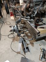
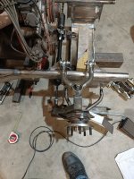
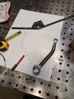
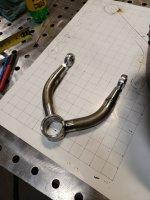
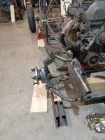
Had everything mocked up and asked Jeff to help tack the mounts on. The weight of the spindle kept causing the stuff to twist so I would hold everything in alignment while Jeff tacked the mounts to the frame. I went over and got the welder and set it up, Jeff sitting beside the chassis, turned around to turn on the welder and gas supply and just froze. After a minute or two Jeff asked if we were gonna do this thing or not and I said no, something wasn't right with the setup. The upper arm mounts should be centered over the chassis tubes and they were hanging over the inside edge. I went back and started checking things and when I had laid out the upper arms on paper I plotted the ball joint, counted up six and a quarter inches from that, then marked three inches on either side of that mark to give me the five inch spread to clear the shock. For reasons I still can't comprehend though I added another inch to those marks to make them seven and a quarter inches from inside mount to outside mount and made both arms to this incorrect length. If you zoom in on the picture with just the upper arm laying on the paper you can see the tic mark centered between the two legs an inch closer to the outside joint than the holes in the heim joints.
There was no way I was leaving that mistake last night even though it was five and everyone else was wanting to head home for the weekend. We cleaned up there and I took the arms across the street and set about fixing things. Luckily the tubing adapters are so long I was able to simply cut the ends off those to shorten things back to the proper length. I finished the welding on the upper arms and added the plate to the lower arms which will mount the shocks with the addition of a couple tabs to be added later. The arms themselves are otherwise completely assembled now though. The Johnny Joints (ball joints) weren't completely assembled when the mock up pictures were taken which is why there is nearly no gap from the upper arm to spindle.
I hadn't ever worked with this type of joint before, and to be honest I'm not sold on them in this application. The claim of 30 degrees of available deflection seems pretty ambitious. I measured 28 with the joint assembled in the arm measuring off a rod inserted through the bolt hole in the joint. That was with the center of the joint bottoming out against the washers that hold the joint together too, but even before that the center butts hard against the rubber cups that hold the ball section of the inner sleeve. So to get to that 28 degree number you have to physically displace the rubber that allows the joint to deflect in the first place. PLUS that 28 degrees was measure off the rod through the hole and not on a plate bolted to the joint. Any plate bolted to the joint will contact the casing sleeve of the joint before you get to that 28 degrees unless you space that center bit up off the plate.
That last bit there causes slight problems in the same way the tire contact to the control arm under full steering lock does. Yes there are ways around them, I can run wheel spacers and get more tire clearance, and I can put spacers between the joint and spindle to get that articulation back. Both of those things are unaccounted for in the design though and will alter the suspension and steering geometry slightly. The articulation issue must be solved first and foremost, so there will be spacers there and there isn't much else to be done now cause I aint rebuilding the spindles. The tire spacers though is a maybe. I've got a set of I think quarter inch spacers laying around and plenty of lug stud to use them. That will increase scrub radius negatively impacting steering feel for what is likely little additional steering angle. I'll probably just try them and see what sort of change it makes or maybe just keep them in my back pocket for a rainy day later.
Immediately started on the control arms because I was (am) excited to see arms on the car. New bender worked like a charm and things basically worked as planned with it. The lowers bent and tacked together we test fit them to try and check for interference issues under steering. Took two people obviously with no upper arms at that time and done up found that the way the leading edge of the lower arm is done there was tire interference to the lower arms. Then it was lunch time. I'm not sure how that happened, honestly I was just working and it felt like I had only been there 45 minutes or so but it had been nearly three hours.
I had designed in 41 degrees of steering...on something. The 41 number I remember but I can't recall if that was inside tire, outside tire, or an average. What I've got here before the tire touches the control arm is 35 degrees on that outside tire. I want more but 35 isn't really the end of the world. The other bit to that is while the suspension obviously isn't assembled and I haven't mounted the shock, it looks like any more than 35 on the outside tire will cause the brake caliper to touch the shock so there's that.
Back from a lunch I largely skipped I laid out the upper arms while Corey drew and cut the upper arm mounts. Bent some more tubing to make the arms and then we all had a good laugh because the actual tubing sections for the upper arms are only 4 or 5 inches long. Everything else is tubing adapter and heim joint. So went ahead and did 4 tiny tube sections and welded them to the center joints in a wide enough arrangement to allow the shock to go up through the middle and went to mock everything up and weld on the upper arm mounts to the frame.


Had everything mocked up and asked Jeff to help tack the mounts on. The weight of the spindle kept causing the stuff to twist so I would hold everything in alignment while Jeff tacked the mounts to the frame. I went over and got the welder and set it up, Jeff sitting beside the chassis, turned around to turn on the welder and gas supply and just froze. After a minute or two Jeff asked if we were gonna do this thing or not and I said no, something wasn't right with the setup. The upper arm mounts should be centered over the chassis tubes and they were hanging over the inside edge. I went back and started checking things and when I had laid out the upper arms on paper I plotted the ball joint, counted up six and a quarter inches from that, then marked three inches on either side of that mark to give me the five inch spread to clear the shock. For reasons I still can't comprehend though I added another inch to those marks to make them seven and a quarter inches from inside mount to outside mount and made both arms to this incorrect length. If you zoom in on the picture with just the upper arm laying on the paper you can see the tic mark centered between the two legs an inch closer to the outside joint than the holes in the heim joints.
There was no way I was leaving that mistake last night even though it was five and everyone else was wanting to head home for the weekend. We cleaned up there and I took the arms across the street and set about fixing things. Luckily the tubing adapters are so long I was able to simply cut the ends off those to shorten things back to the proper length. I finished the welding on the upper arms and added the plate to the lower arms which will mount the shocks with the addition of a couple tabs to be added later. The arms themselves are otherwise completely assembled now though. The Johnny Joints (ball joints) weren't completely assembled when the mock up pictures were taken which is why there is nearly no gap from the upper arm to spindle.
I hadn't ever worked with this type of joint before, and to be honest I'm not sold on them in this application. The claim of 30 degrees of available deflection seems pretty ambitious. I measured 28 with the joint assembled in the arm measuring off a rod inserted through the bolt hole in the joint. That was with the center of the joint bottoming out against the washers that hold the joint together too, but even before that the center butts hard against the rubber cups that hold the ball section of the inner sleeve. So to get to that 28 degree number you have to physically displace the rubber that allows the joint to deflect in the first place. PLUS that 28 degrees was measure off the rod through the hole and not on a plate bolted to the joint. Any plate bolted to the joint will contact the casing sleeve of the joint before you get to that 28 degrees unless you space that center bit up off the plate.
That last bit there causes slight problems in the same way the tire contact to the control arm under full steering lock does. Yes there are ways around them, I can run wheel spacers and get more tire clearance, and I can put spacers between the joint and spindle to get that articulation back. Both of those things are unaccounted for in the design though and will alter the suspension and steering geometry slightly. The articulation issue must be solved first and foremost, so there will be spacers there and there isn't much else to be done now cause I aint rebuilding the spindles. The tire spacers though is a maybe. I've got a set of I think quarter inch spacers laying around and plenty of lug stud to use them. That will increase scrub radius negatively impacting steering feel for what is likely little additional steering angle. I'll probably just try them and see what sort of change it makes or maybe just keep them in my back pocket for a rainy day later.
Would feel much better about this here if I didn't uncover a potentially catastrophic problem here. The steering rack is a front steer unit, when everything I've done is rear steer.
Can you invert the rack?View attachment 203477 View attachment 203478
Would feel much better about this here if I didn't uncover a potentially catastrophic problem here. The steering rack is a front steer unit, when everything I've done is rear steer.
Apparently this ain't the first time this dilemma's popped up. 
http://www.colemanracing.com/Reverse-Drive-Gear-Box-P6316.aspx


http://www.colemanracing.com/Reverse-Drive-Gear-Box-P6316.aspx
Apparently this ain't the first time this dilemma's popped up.
http://www.colemanracing.com/Reverse-Drive-Gear-Box-P6316.aspx
Fantastic, I was hoping someone made something like that. It's cheaper than I would've expected too. I've been sitting here for the last couple hours scouring for a rear steer rack and pinion that fits what I've got and couldn't find squat. Driving home I was thinking that if I could gear drive the input shaft it'd invert the steering but wasn't thinking of anyone just making that, I was thinking I'd have to make it if worst came to worst. You would think there would be more of an option for manual steering racks out there but the only thing I can find rear steer that fits dimensionally is for a Dodge Omni and the total travel and ratio both suck.
It's a fancy steering reverser doodad
Seems I saw that thing some place else recently??????????????
Seems I saw that thing some place else recently??????????????
Three post up. ↑
but this one has a fancy California Cancer notification sticker
It seems everything in California is immoral, illegal, fattening, or causes cancer. Is it just lab rats, or everybody else?... 

Well then don't be chewing on that gear box and keep the lab rats away!but this one has a fancy California Cancer notification sticker
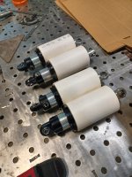
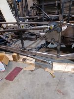
Put the shocks together before lunch today and added my pieces of tube for spring stand ins that I cut last week. That done I focused on getting the lower four link bars mounted. By lunch time I had a reinforcement bar welded in and a triangular plate with a nut welded on tacked in place. Funny story, I took vacation days for the week so I slept in a bit this morning not having to be there first thing. When I actually looked at my phone right before I left the house this morning I had a text from one of the guys saying he got a piece of wood in his eye yesterday and wouldn't be in today but didn't have the shop helpers number to let him know. About an hour after he sent that I got a message from the shop helper asking where the hell everyone was.
Even though the shop was supposed to be open today, the shop helper was the only person who actually showed up for work this morning. By the time I stopped to get some tools he was gone too. I ended up opening the door for a couple deliveries I just happened to see, so I did more work on a vacation day than the rest of the shop put together when they were supposed to be working. That is to say that it was lunch for me but a late lunch, which I don't suppose is really worth knowing.
After lunch I made the bar and plate for the other side then got both plates fully welded. The wheel base is set at 108.5 and the pinion angle is just a shade off zero which matches the mounting plate part of the transmission. The four link bars ended up at 5 degrees after all with no weight on the tires so that's an unexpected bonus to things.
The plan for tomorrow then is to be able to finish weld the engine mounts coming off the frame and finish the transmission mounting. I've got some tubing to cut and sleeve the box section that makes the trans mount so I'll have to enlarge the holes in the box section and cut the sleeve pieces and weld them in. That way I can put torque on the mount bolts without just crushing the box section pieces.
Similar threads
- Replies
- 22
- Views
- 3K


