1974 TX650A Restoration Project

I can only imagine how frustrated you may be that the frame will not fit in your blaster!
I am not joking when I say I spend the better part of 20 minutes trying to figure out a magic angle to squeeze my front rim in there :laugh:


The '74 was probably the lowest production of all the 74 up models, some say about 12,250 units.
Funny you say that, there was literally one posted on New Hampshire craigslist this morning that was factory original with 11k miles for $1200 obo. It's already gone.
4C9EAB4F-CF3F-47CD-854C-492A46BD95C5.jpeg
 
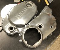
Crankcase covers:

I probably should have realized after doing my cases that the case covers were going to be tough to vapor blast with my set-up. They're large, flat areas that would be hard (for me at least) to get a consistent finish on with the gun I have (Imagine trying to sand a case cover to a consistent finish with an abrasive Q-tip). So they came out OK, not great, as you can see from the pics.
IMG_1779 (2).jpg
IMG_1780 (2).jpg
IMG_1781 (2).jpg
IMG_1789 (2).jpg

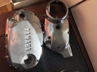
I decided to actually take vapor blasted case covers and buff them out a bit using just brown and white compounds on a bench grinder, then finish by hand with some Autosol. I don't know what it is.... I've tried Noxon, California Purple Polish, Blue Magic, but I still think Autosol is the best. What do you guys like for metal polish?
IMG_1804.jpg
IMG_1921 (2).jpg

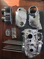
So with that, I had my case covers, top end assembly, tappet covers, advance/points covers, breather, cam adjuster cover all cleaned up, and ready to start reassembly (this was probably early January....I'm maybe a little behind where I wanted, but not too bad).
IMG_2185.jpg
IMG_2186.jpg
IMG_2187.jpg


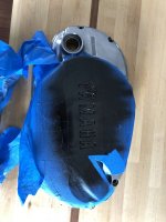
I also toyed with the idea of keeping the debossed YAMAHA natural, but I opted to fill in w/ rattle can gloss black. I think overall they came out pretty nice, and I think the semi-mirror finish will be a nice contrast to the satin finish on the other components. I still need to do the rotor cover on the other side to match. What do folks think on the black versus natural? I went back and forth.
IMG_2979.jpg
IMG_2980.jpg
 

Attachments

  • IMG_1921 (2).jpg
    IMG_1921 (2).jpg
    199.2 KB · Views: 174
  • IMG_2185.jpg
    IMG_2185.jpg
    207.4 KB · Views: 172
  • IMG_2187.jpg
    IMG_2187.jpg
    142 KB · Views: 202
  • IMG_2186.jpg
    IMG_2186.jpg
    157.3 KB · Views: 189
  • IMG_2979.jpg
    IMG_2979.jpg
    174.4 KB · Views: 204
Powder coating:

Since I'm doing this chronologically, I should probably talk about what was happening in parallel right about now. One of the main drivers for this project at all was the frame. The paint on the frame was in pretty rough shape, and I knew that no amount of waxing/cleaning the bike would make this anything but what my Dad would have called a nice "10 foot bike" with the paint and light rust spots on the frame the way they were. So the catalyst for this whole project was really powder coating the frame. Some 'before' pics below where you can see her age showing.
IMG_1605.jpg
IMG_1609.jpg
IMG_1612.jpg
IMG_1608.jpg

When I had the bike down in the basement, I put the frame in a giant cardboard box and started scraping 45 years worth of crud off of it. It's not until you do it, do you realize how many places there are for crud to hide! I cleaned it up, and found a local company that would do the powder for me (Nationwide Powder Coating, Billerica MA. Great guys!). I also pulled a whole host of other smalls together to do at the same time to make my life easier. Including - swingarm, battery box, air boxes, triple trees, front disc brake rotor mount (star-shaped disc-looking thing), motor mounts, and rear set/exhaust mount brackets. I have a little Eastwood powder coating set-up that I bought last year with a buddy that I had already used for the center stand, side stand, and front pegs, so I didn't have those done, but sort of wish I had, because I think Nationwide does a much better job than me, but oh well.
59978129634__6E07ACC3-7B7E-4E29-B4D3-F363909A2F89 (2).jpg
IMG_2411.jpg
IMG_2417.jpg
IMG_2423.jpg

I got the parts back less than 2 weeks later, and I was very happy with the results. Some sample pics below of some of the components.
IMG_2584.jpg
IMG_2583 (2).jpg
IMG_2576 (2).jpg
IMG_2575.jpg
 
To answer a couple of your questions, I’m a Blue Magic guy, love that stuff!
I like the Yamaha letters painted black versus natural ( I’ve had them both ways )

And your powder coating came out great! You got a very fast turn around time from your shop. I’m curious, did you remove your steering lock prior to sending it to the powder coater? Or did yours get melted solid like mine? :laugh2:
 
Thanks Bob! Yeah, had great luck with Nationwide, they were great to work with. Funny you say that.....my steering lock was non functional so I forgot about it when I sent it off. When I picked it up, the guy was really excited to show me that he kept the protective metal 'flap' over the lock assembly and that it still opened and shut. I didn't have the heart to tell him the lock was broken. Turns out though, I popped it out when I installed the steering assembly and cleaned the hell out of it, and actually got the damn thing working again. I would have never believed it haha.
 
Bottom end reassembly:

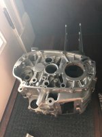
With my parts cleaned and new oil seal kit and assembly lube in hand, I started putting the motor back together. Lots of really helpful threads here in the forums helped to fill in where the Clymer and repair manual were lacking. First was the shift fork guide rod (bonus points to the forum for highlighting the ability to put this thing in backwards, with the open end facing outwards) and the shift drum. This took some careful work to make sure the "track" followers that ride in the shift drum channels and guide the shift forks, were 1) seated in the channels and 2) had their holes aligned for the cotter pins. I spec'd the cotter pins per the parts manual, but they seemed a touch longer than the ones I remember removing during disassembly. Something to watch for here is to make sure the free ends are rolled around or otherwise out of the way at ALL points in the movement (i.e. all the gears). As you can see from the pictures, the furthest one (in the middle) is sort of hard to access.
IMG_2285.jpg

IMG_2297.jpg

IMG_2286.jpg
IMG_2287.jpg
IMG_2288.jpg
IMG_2289.jpg

Next step was the shift star assembly on the drum. I replaced the spring here, as I saw lots of reports of this being responsible for shift issues and/or false neutrals.
IMG_2293.jpg

Here's a terrible video of me running through the shift fork movement by hand.


Next step was to give the transmission another visual check, replace the oil seal, and pop it back in. Light coating of Permatex Form-a-Gasket aviation liquid sealant on the bearing/oil seal surfaces.
IMG_2360.jpg
IMG_2361.jpg
IMG_2362.jpg


Now, time to install the cam chain, new oil seal on the crank, and install that. Point of note is to make sure the positioning 'half-ring' that seats on the crank bearing is in place.
IMG_2363.jpg
IMG_2364.jpg

Here's a little vid of me turning everything by hand to make sure all was moving freely

I had every intention of re-installing the starter, so I also put that gear assembly back together and installed
IMG_2366.jpg
IMG_2367.jpg
IMG_2368.jpg


I didn't take any pictures, but there's a light coat of sealant on the mating surfaces, then I closed the halves and buttoned it all back up using the specified tightening pattern. Use the torque specs....they're not nearly as tight as you might think. (Please disregard my 'can stand' hahaha). After it was all torqued, I parked in the really high-tech engine stand I build for the rest of the reassembly
IMG_2371.jpg
IMG_2372.jpg
IMG_2373.jpg


That wasn't so hard after all!!
 
Last edited:
Thanks Bob! Yeah, had great luck with Nationwide, they were great to work with. Funny you say that.....my steering lock was non functional so I forgot about it when I sent it off. When I picked it up, the guy was really excited to show me that he kept the protective metal 'flap' over the lock assembly and that it still opened and shut. I didn't have the heart to tell him the lock was broken. Turns out though, I popped it out when I installed the steering assembly and cleaned the hell out of it, and actually got the damn thing working again. I would have never believed it haha.

Its a small thing - but I use my steering lock all the time. I just feel it may give me an extra couple of minutes to get back to the bike if some twit is trying to steal it.

Somerville - you bike is going to be a beaut!
 
Its a small thing - but i use my steering lock all the time. I just feel it may give me an extra couple of minutes to get back to the bike if some twit is trying to steal it.
You know, now that I have it working, I actually imagine I'll use it all the time.

Thanks Pete! It's coming along. I have a couple more posts to bring this story up to real time. Everyone's feedback has been awesome. Wish I had motivated myself to start this earlier..
 
Hey Somerville, I just wanted to add to the many that have commented to say that your article and pics are second to none. Great work. I just sold a XS hardtail to a young man near Teele Sq/Tufts. I would be cool to see a few more of these machines on the roads around Boston.........

tim
 
Starter motor:

So, I had done the whole bendix replacement early last year, not too long after I bought my bike. It's obviously a well established problem and the fix for it is pretty well established as well here on this board. My starter was weak and also had the tell-tale fork in the garbage disposal sound, so I just bought the replacement kit from Mikes assuming that the gear had some wear on it from the weak spring, figuring I might as well replace it while I've got it opened up. I did the repair, and compressed the wishbone spring, but I suspected it wasn't quite enough, because I still had kick-out problems. I should have tried to measure the force on it, but hindsight, etc etc. So I found some good threads and info in the manual on refurbishing a starter. I broke it down, cleaned the commutator, filed the insulating mica in-between, degrimed the hell out of it, cleaned and painted the body and vapor blasted the end caps (yes....I'm insane...). When I put it back together spun like hell when I powered it up, so I feel like I at least fixed that part of the problem. And I can also say I might have the best looking starter motor around :shrug::doh: :laugh:
IMG_2356.jpg
IMG_2988 (2).jpg
 
Thanks everyone, the feedback is great. It's a lot more encouraging than the polite nod I get from my wife when I tell her about a milestone I've met hahaha.

Hey Somerville, I just wanted to add to the many that have commented to say that your article and pics are second to none. Great work. I just sold a XS hardtail to a young man near Teele Sq/Tufts. I would be cool to see a few more of these machines on the roads around Boston.........

Thanks Tim! You know, I've never seen another XS in the wild although, I am pretty new to motorcycling. This is my first bike, in fact.

Teele/Tufts is about a mile from me here in Magoun/Winter Hill, that's awesome! I'll have to keep an eye out.
 
Top end - pistons and jug:

With the bottom end reassembled and seemingly in good shape (fingers crossed), it was time to start working on the top end. As mentioned previously, my timing was fortunate, in that Hoos Racing had recently started selling their new cam chain slipper, which saved me the trouble of going down Jim's route of fashioning my own with a replaceable rubber. Another shout out to this forum, as I knew from other threads that the slipper has some lateral play in the cam chain tunnel and that it needs to be secured while tightening it down to ensure it stays centered. I'm not sure I would have realized this if not for the threads, so good looking out all! BTW, does anyone know why this is? Seems like a design flaw for it not to be positionally keyed or something, but maybe there's some non-obvious feature there I don't understand. Made sure to replace the o-rings around the bottom of the cylinders as well, which is a mistake I can see easily making.
IMG_2468.jpg
IMG_2469.jpg
IMG_2470.jpg
IMG_2471.jpg


Quick note on the cam chain tensioner that may be useful for folks....I saw reference to this in other threads, but didn't see pics, so maybe this is my one addition to this community. If you're installing an endless cam chain like I am, you'll quickly realize that you need to thread the chain through the mount/hinge of the tensioner assembly. Key here, as stated by others, is to drill out one side of the horizontal bar that runs through the mount, so you can pry the two sides open and slip the cam chain inside. You can see a couple pics below. If you use a 7/16" drill bit, you can juuuuust knock off the flared end of the rod enough so you can remove it from the mount, but it still has enough 'meat' on the rod to insert back into the hole snugly. This made the assembly feel a whole lot more robust than I expected and felt like a pretty clean install. I know folks say that that bar isn't even necessary at all when it's installed back in place, but anytime I can leave as little a trace as possible, I'll take it! So I installed this back into it's home over the crankshaft.
IMG_2379.jpg

IMG_2378.jpg

IMG_2382.jpg
IMG_2394.jpg

Installed the gasket
IMG_2395.jpg

I didn't do anything elaborate to reinstall the pistons, Jim's seminal top-end thread was key, and I used a variant of Bob's popsicle stick technique (plastic paint scraper maybe?) to compress the rings for install through the bottom of the cylinders. They went in without too much trouble after giving a light finger swipe of oil around the inside of the cylinders. Made sure both pistons were on their respective sides and facing forward per the arrows on the faces. I fed the cam chain up through the tunnel in the head, and zip tied in place for safekeeping. At this point, support the jug so that the connecting rods can be installed (I personally went with the two rolls of painters tape/rubbing compound combo.....an 'unconventional' choice....), and definitely block off around the connecting rods with rags/non-linting towels, whatever because you will be very mad with yourself if you drop a wrist pin down into that black hole!
IMG_2388.jpg
IMG_2472.jpg
IMG_2473.jpg
IMG_2474.jpg
IMG_2475.jpg

Voila! Onto the head!
 
Your usual nice work! One thing I saw, and maybe you’ve already addressed this. But the spot I’ve circled here, is where they’ve sealed off an oil passageway. They first plug it with a ball bearing and swage it in there, then seal it off with epoxy. There are a number of these passageways in your motor and sometimes the epoxy gets old and flakes off. Just mix up some JB Weld metal epoxy and smear a dab on there. If you haven’t already done so, that is. :thumbsup:
726D959A-A7B4-47AA-B8C0-DEA461AA4C04.jpeg
 
But the spot I’ve circled here, is where they’ve sealed off an oil passageway.

Hi Bob, that is actually something I did NOT do or notice, so thanks for the tip! Looking back at the tear-down pics I see it was on there previously, so I must have blasted it right off. Thanks!!
 
The half ring on the crank bearing in which portion of the engine does it sit? Does it face up and top case sits or down and drops in with crank being lowered

Thanks Superjet! You know, I actually don't remember what I ended up doing.... I took a lot of pictures during this process, but I actually got much worse at remembering to do it as reassembly went on. The pics I have in my post above aren't helpful, because as you might imagine, I had to remove the trans and crank to gasket seal the cases, so I'm not sure what I actually ended up doing, although I have a vague recollection of seating in the top half (which is upside down during reassembly) with a portion of the ring extended to mate with the other half.

To 2M's point.....I went back and looked at my teardown pics, and saw that both the trans and crank seemed to be like he suggested....And I don't think this motor was ever opened, so I assume that was from the factory.
6CF950F2-60EE-4C8C-8BBE-7B4148F875DA.jpeg
68F343A0-E1E3-4015-8591-A33D140104C4.jpeg
 
Top end - Valves, Cam and Followers:

Cleaned up the valves as best I could, but have to say they don't seem to get nearly as clean as everything else. I tried my hand at valve lapping. I made a video of my technique for doing this, using techniques described on this forum and some internet videos, and it seemed to be pretty effective. I was looking to see a consistent polished 'face' around the valve and in the seat. After lapping, I didn't see any pits, so I assumed this meant my valves were sufficiently lapped.
IMG_1837.jpg
IMG_1835.jpg
IMG_1877.jpg
379D9DC1-FF82-4200-884C-0E465DA565C0.jpg

I went back and forth on trying to DIY it or actually buying a valve spring compressor, after seeing quite a few clever solutions posted across this forum and elsewhere. I think I found one for like $16 shipped, and while I know it's not exactly an heirloom tool, this felt like money well spend for this build, especially considering I don't have a welder here. I checked the free length of the springs and all were within spec, so felt OK to reuse. After re-installing the valves, I did a leak test using some mineral spirits in the ports. I saw some light seepage after a few minutes, but nothing drastic, and given the wicking properties of a solvent like that, I don't know that I would expect a perfect seal forever anyways. Some before and after pics are here as well.
IMG_1879.jpg
379D9DC1-FF82-4200-884C-0E465DA565C0.jpg
158C25FE-C876-4949-9A17-262339426000.jpg

Then install the head
IMG_2477.jpg

Reinstalling the cam was pretty straightforward, paying close attention to the timing mark on the sprocket at 12:00 as well as the dot lining up with the head at 9:00. Jim's top end thread does a great job illustrating this. It was a little fussy getting the endless cam chain around the sprocket and I used some sockets to lightly torque down the head to give some extra play, and then slip the dual bearings over each end.
IMG_2482.jpg
IMG_2483.jpg
IMG_2496.jpg
IMG_2497.jpg
IMG_2478.jpg

Follower/rocker arms was next....straightforward EXCEPT to make sure the shafts are facing the correct way with the threaded access hole facing out. Not sure if they can go in the other way (?) but it seems like it would have been a really regrettable mistake to get that wrong. Little assembly lube on each before install.
IMG_2494.jpg
IMG_2499.jpg
IMG_2500.jpg

IMG_2533.jpg

One tip I found that was very helpful was (I believe) in Jim's thread.....re-installing the points/advance housings on each end of the cam shaft to center the cam and bearings before torquing the head bolts down with the specified torque pattern. You can see the new rubberized washers I opted for, although they were a little pricier than the copper ones I've seen others use.
IMG_2535.jpg
IMG_2539.jpg
IMG_2505.jpg

Motor is almost done and nothing has cracked or exploded (yet!). I was feeling both accomplished and apprehensive at this point, but I could turn the crank by hand (well, strap wrench) and everything moved freely, so I felt that was at least headed in the right direction :D
 
Back
Top