1981 Yamaha XS850 Special not charging battery

domsob1974

XS650 Member
Messages
8
Reaction score
2
Points
3
Location
South Bend, Indiana
Greetings,

I am slowly reviving this old XS850 and I noticed today that when I have it running, even if I am bringing the RPMs up to 5k, I get no charging voltage back to the battery. What do you think? Take apart the connections and clean? Classic Reg/Rec issue? Alternator? The wires under the seat have been ... umm.. modified by the last owner, but I don't see any broken connections.


Thanks in advance
 
I have an XS1100. Perhaps it's similar enough to the XS850. On my 1100, the fuse box is under the right side cover. Under it is a six wire connector, IIRC. Anyway, one side of that connector goes to the stator. You need to access that connector and examine it for heat damage and corrosion or heat damage and dielectric grease. It's not uncommon on the XS1100. That failed connector begins as no charge and ends failed stator. On mine, I replaced the connector and almost a foot of wire on each side. Same thing on my XS650, though I only replaced the connector and pins on that one.
 
Throwing some pictures here for context. I don't see a fuse box/block by the battery or where either one of the side panels used to be. What is this rectangle thing with two connectors on it (in the pics). When I shake it, it sounds like a maraca. I am sure it isn't the issue, but that can't be good. I tried the "clank test" with a wrench, screwdriver, and by turning the ignition on and off. The wrench doesn't move. In the morning, I am going to pop off any chassis grounds I can find and clean them real good. I put that inline fuse in it after looking at a couple of threads (mine is had it ran straight on with some electrical tape at the union.
 

Attachments

  • 111.jpg
    111.jpg
    116.8 KB · Views: 296
  • 222.jpg
    222.jpg
    132.3 KB · Views: 269
  • 333.jpg
    333.jpg
    83.9 KB · Views: 230
  • 444.jpg
    444.jpg
    168 KB · Views: 392
  • 555.jpg
    555.jpg
    205.6 KB · Views: 314
I don’t recognize that component. Find the wires coming off the stator. Follow them up to the first connector and examine it closely.
 
Update (sort of)

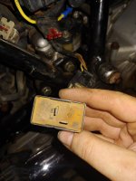
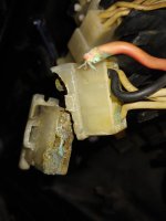
I started unhooking all of the wire connectors on the side opposite the solenoid (cleaning the connectors with contact cleaner and a little flat head screwdriver) and I found that the rectifier/regulator plug was pretty bad. So much so, that a wire broke off the moment I touched it. (See pic). Now, They were slowly breaking off one-by one, so I cleaned with contact cleaner and crimped new connectors on each individual pair so as not to confuse (there were 3 white wires, 1 black and 1 red). I made sure to insulate (electrical tape) each newly paired and connected pair and then insulated the whole bundle. I turned on the ignition and started the bike. She started (I affectionately named her Big Red), and I hooked up my multimeter and gave a little bit of throttle. She was charging. I say 'was' because I should have inspected the condition of the regulator better before firing her up (it looked like something raised from the Titanic). The voltage never got beyond 13.8 volts before the regulator started bellowing 'magic smoke'. I shut her down immediately and surveyed the damage. I turned on the ignition and there was nothing (no Neutral light) Luckily, I looked at the post that was at the beginning of this thread and had the foresight because of it to put an inline fuse in (see pictures earlier in the thread). It popped the 10A fuse that was in it (QUESTION - Should it be a 10A fuse that is ran off the solenoid or something bigger?). After putting a new one back in the neutral light was back on and a VERY quick tap of the start button and the starter actuated. So, I am guessing that the regulator 'gave up the ghost' and at first, only broke/melted the red wire off of the connector before I got it. When I gave good solid connections, it decided to give me a fireworks display. I will be ordering a new regulator online, but I have a question. (also, comments are welcomed).


Is there a place (or individual) who makes a pigtail for the connector that was FUBARed? Something that I can just crimp inline. I would hate to get a new rectifier only to have to chop the end off to mate it to the spade connectors I was forced to put inline.

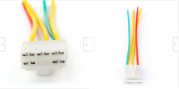
NOTE - I ended up ordering THIS (see Pic 2). The colors are different (the whites are yellow and the black is green), but the pin out looks the same (It is for a XJ600 and like 70 other bikes) and the connector tab is on the correct side. I just don't know if it is physically the same dimension. I guess we will find out. If so, then I hope this helps someone else. The Rectifier comes tomorrow, but I will wait for the connector to come before I put power to it. I will keep everyone updated.

Thanks in advance.
 

Attachments

  • rectifer wire.jpg
    rectifer wire.jpg
    60.5 KB · Views: 186
  • pinout.png
    pinout.png
    225.7 KB · Views: 161
Last edited:
There are 2 thin wires that run from the alternator back to the regulator. They run in a very exposed route that is prone to road debris damage.
On my 850 that is a long term project when stripping the bike I found that these were both broken. Check that these are not shorted or you may toast your new regulator.
Can you elaborate a little further on the route that those wires take?
 
They exit at the bottom of the outer alternator cover and follow the lower right hand frame tube. There is a shorter ground wire and two longer ones that travel to the regulator. The cables supply the inner winding of the alternator.
 
They exit at the bottom of the outer alternator cover and follow the lower right hand frame tube. There is a shorter ground wire and two longer ones that travel to the regulator. The cables supply the inner winding of the alternator.
Thanks for the details. I will definitely be checking those out before hooking everything up. I am considering maybe using some small steel braiding to help strengthen and protect from road debris.
 
I just thought of something. Since I put new connectors on those wires and three of them are white, I wonder how I am going to know which white wire goes where and comes from where. Hmmm.. this could be "interesting".
 
Doesn't matter.... any white to any white. Each white is one phase of a three phase stator. The rectifier doesn't care which is which.
 
From the service manual to test the Reg/Rect. For the 750D but should be the same to test all SS Combined Reg/Rect.............I'm sure if there is something wrong Jim or someone will correct

Rec Test01 resize.jpg Rec Test02 resize.jpg Rec Test03 resize.jpg
 

Attachments

  • XS850G.PDF
    722.5 KB · Views: 193
I'm sure if there is something wrong Jim or someone will correct
thumbsup.gif


That's an interesting design. The field coil (4) is fixed in place... doesn't spin. There's a fingered iron rotor (2) that rotates around the field coil. The field current creates a magnetic field in the rotor and that's transferred to the stator (3)..... thereby eliminating the need for brushes. Bloody brilliant. I've seen something similar on large aircraft generators but nothing this small scale before. The return side of the field coil is tied to the load so that as electrical loads increase, field strength increases. I like it.... a brushless alternator that isn't a PMA.


Untitled.png
 
Back
Top