Help with Mikes xs reg/rec and simple wiring harness!

dean martin

XS650 Enthusiast
Messages
34
Reaction score
0
Points
6
Hey everyone, looking for insite. Building first bobber and down to the wiring. Just a basic harness needed. Trying to follow a basic schematic found on many sites but the wiring does not match what my reg/rec has. I have 3 yellows, green, red, orange and blue? No one shows a blue anywhere. My alternator has 3 whites, green, black and blue and yellow? I know the 3 yellows go to the 3 whites and my red to the battery and the yellow from the alternator is not used but after that....HELP!
 
Sounds like you have a Mike's reg/rec. I don't have or will I ever use one of his reg/recs. I have read lots of questions about how they should hook up. Not too many answers. Depending on the year of your bike will depend on if it works.
Mike's as well as other companies sell uneversal fitment reg/recs. Some fit the early bikes, some work with just the later bikes.
From what I have read the 3 yellow hook to the 3 whites. The red is hot to battery, green ground, The blue and orange go to the brushes.
Other than that I have no answers about it.
I use a Chrysler regulator with a Radio Shack rectifier. Works very well and cost about $30 to build.
Check the tech section on here or the electrical section over on the Garage. Tells all about the conversion and many testimonials on how easy to do and how well it works.
 
Thanks for the info. What do you mean by brushes? Would that be the 2 remaining wires of the alternator?
 
The brushes are part of the alternator. I guess I can explain it.
On the 650 it uses what is called a feild excited alternator. The feild is the magnetic feild that excites the stator to produce electricity. Thus feild excited.
To make this feild the rotor needs power from the battery. This power flows To the rotor through brushes.
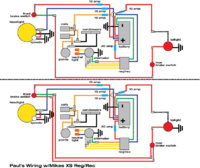
On the early models 79 and older, when you turn the key on power flows to the regulator on the brown wire, from the rgeulator to the positive brush, through the rotor out the negetive brush to ground at the stator housing and the black wire to the wiring harness.
This creates a strong magnetic feild around the windings in the stator. Now when you start the engine, Now with the rotor spinning the stator starts to make electricity. At idle it won't make much electirity, as you rev the engine it makes more, This will run the bike and have some to charge the battery. The regulator reads the battery voltage, when the alternator gets the battery voltage up to the preset value, 14.5 volts, it shuts off the electricity to the rotor. As the bike runs it uses electricity, when the battery voltage drops below the preset voltage, 14.5 volts, the regulator turns the rotor on, it does this hundreds of time a second. This is how the regulator works.
On the 80 up bikes the regulator does the same thing, turns the rotor on and off, it just does it a bit different. The bike is wired a bit different. It sends power to the regulator on the brown wire but also to the positive brush. From the positive brushe through the rotor to the negetive brush. Now instead of grounding here power goes to the regulator on a green wire. Inside the regulator is a transistor the is contoled by battery voltage. When the battery voltage is below 14.5 volts the transistor turns on and grounds the rotor. This makes voltage, when the battery voltage gets above 14.5 volts the transistor shuts off. Turning the rotor off.
On you bike depending on the year the alternator needs different types of regulators.
You need to know what type you need and what type you have.
If yo have an 80 or later type alternator then where the wires come up to the connector, the green and brown wires are the brush wires. I think if you hook the blue and orange from the reg/rec to the brown and green from the alternator it might work.
I've never used a Mike's reg/rec so I'm kinda guessing here.
If you want to wait until someone with a bit more experence with one chimes in, fine.
If you do get it working, would you post just how you wired it so the next person with one can find a wiring that works?
I for one would like to know.
 
Thanks for all the input. Does this make sense? It's a 78xs. Want to run with key only.
 

Attachments

  • PaulsWiringDiagram.fuses3.jpg
    PaulsWiringDiagram.fuses3.jpg
    48.3 KB · Views: 161
It looks like it should work ok as far as the reg/rec goes. If it doesn't then you might want to contact Mike's and see if they can tell you just how to hook it up.
The brake switches are wired wrong. Power goes to the switch then to the brake light and grounds at the bulb socket.
If you look at this diagram you will see that power goes to each brake switch on the brown wire, then to the brake light on the yellow wires'
 

Attachments

  • 314w9s3.jpg
    314w9s3.jpg
    135.4 KB · Views: 119
Thanks xsleo! Here is my updated schematic if you would not mind taking another look.
 

Attachments

  • PaulsWiringDiagram.fuses4.jpg
    PaulsWiringDiagram.fuses4.jpg
    50.5 KB · Views: 122
With that one your tail light and brake light will both come on together when you hit a brake switch, but you won't have a tail light normally on. Put the two brake switches in parallel going to the brake filament, and connect the tail light filament directly to the switched side of the key switch.
 
Thanks for the help. Does this seem correct? Not sure if the red or bk/wt is the tail light filament or if it matters.
 

Attachments

  • PaulsWiringDiagram.fuses5.jpg
    PaulsWiringDiagram.fuses5.jpg
    49.6 KB · Views: 86
The brake filament will be the filament that's the brighter of the two. Here's the way to do it that I described.

----------------< +12
| |
| |
\ \ the two brake switches
| |
| |
----------------> brake light filament

Notice that with that arrangement either one or both switches will send power to the brake light filament


and for the tail light filament:

+12 >----- key switch here --------> tail light filament
 
Thanks for your patience. I really suck at this. Decided to try 2 versions. If the bottom one is correct I do not understand where the 3rd wire to the switches comes from since they only have 2.
 

Attachments

  • PaulsWiringDiagram.fuses6.jpg
    PaulsWiringDiagram.fuses6.jpg
    103.7 KB · Views: 92
Thanks for your patience.

I gots nowhere to go at the moment.


Neither of those schematics will work. Do you understand the one I tried to draw? Two switches side by side. One wire to each side of switch. one wire of each switch goes to brake filament. The other wire of each switch goes to +12.
 
I thought I did. Made diagram of just the brake switches to take everything else out of the equation.
 

Attachments

  • brakeswitchwiring.V1.jpg
    brakeswitchwiring.V1.jpg
    74.4 KB · Views: 110
That's it except for one thing. Below the two brake switches join those two wires together into one so that only two wires total go to the bulb, and you'll have it.
 
After you do that, a refinement you can make is take the two wires that come from the top of the brake switches and move them both to connect to the wire on the bottom of the key switch. That way the brake lights will only come on if the ignition is on.
 
Tell me it finally sunk in to my thick skull!
 

Attachments

  • brakeswitchwiring.V2.jpg
    brakeswitchwiring.V2.jpg
    76.7 KB · Views: 86
That's it. I just finished drawing the same thing and was going to post it. You beat me to it.
 

Attachments

  • brakeswitchwiring.V1.jpg
    brakeswitchwiring.V1.jpg
    8.6 KB · Views: 91
Great! Now I only hope the rest is ok. Thanks for all the input. It seems it should be much easier than I am making it.
 
It's all easy except for that mysterious rectifier. And Leo validated that part of it, so you're go for launch.
 
Back
Top