The dark arts revisited (or how to correctly wire a regulator recitifier)

Crashedkiwi

XS650 Enthusiast
Messages
58
Reaction score
110
Points
33
Location
New Zealand
Hello all; after your sage knowledge yet again. I'm about to start wiring up this bike build of mine - I brought a new Standard Loom from Heiden Tuning and I have a regulator/recitifer that came with the bike that was sourced from MikesXS. I've read moist of the posts I could find on wiring this guy in - but I'd still like to check that what I think to do, is right. I've attached pics of the wires and connectors; hopefully this will assist. So here goes :
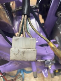
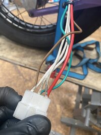
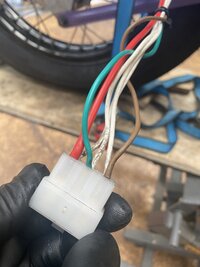
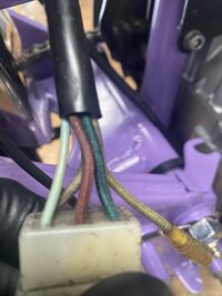
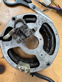
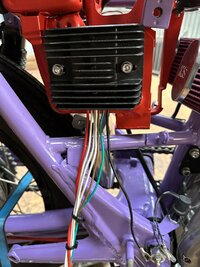
From the stator: I have 6 wires in a wiring block connector , a yellow single wire & and earth wire ( not shown in the pic, but grounded to the frame) My theory is I ignore the single yellow - ie not connect it. I then connect the three white wires ex the stator to three white wires on the rect/reg box in any order. I'm then left with three wires - a light green, a red, and a dark green. I assume red goes to red on the rect/reg - but as the rect/reg has a green and a brown wire; which of the two green wires from the stator goes where? There is also a black (ground) wire ex the rect/reg which I'll ground to the same frame post as that of the stator.

Am I close here / what am I missing ? there is currently nothing else wired anywhere in the loom; I'm starting at wiring in the rect/reg and then off to wire in the the rest.
As always greatly appreciate your collective inputs
 

Attachments

  • Stator view 1.jpeg
    Stator view 1.jpeg
    233.6 KB · Views: 68
  • Rect reg view 1.jpeg
    Rect reg view 1.jpeg
    239.5 KB · Views: 66
  • Rect:reg view 2.jpeg
    Rect:reg view 2.jpeg
    226.1 KB · Views: 66
  • Stator view2.jpeg
    Stator view2.jpeg
    209 KB · Views: 63
You need to tell us which type of alternator you have, the early style or the late style. The brushes are wired differently on the two types and that determines what type of regulator you need. Your old stock alternator plug looks like the later style, going by the wire colors. They are faded a bit but you can still I.D. them. What you're calling light green is actually light blue and comes from the neutral light switch. It will have nothing to do with the regulator. What you're calling red is actually brown and goes to the inner brush. It gets connected to switched power in the harness, not to the reg/rec. The green is the outer brush and will get connected to the green from the reg/rec,
 
Appreciated - the engine ID‘s as an 80-81 Oceania build (5A9-00…). I get the red/brown colour issue; I’ll pull a bit of the outer shroud that wraps the bundle off and see what the colours are in actuality. The brown goes to the switched power; do I take that to mean the fused power feed in the harness?

I guess the other issue I have in reality is as the bike is a custom build, not a stock connect all the plugs to the same plugs job, I need to understand fully the wiring circuit that is required for the bike to run and be compliant with our road laws. For example I’m not contemplating wiring a keyed switch into the circuit; just an engine run/off switch. That, headlights, indications, stop lights and a horn is all I’m after. Oh and a neutral light. I can call time at anytime and call in the auto electrician, but that is not my preferred option; I kinda want to do it myself!
 
Switched power means power turned on and off by the key, not direct power from the battery that would be on all the time. The brown wire coming out of the reg/rec should also be connected to switched power.
 
Switched power means power turned on and off by the key, not direct power from the battery that would be on all the time. The brown wire coming out of the reg/rec should also be connected to switched power.
Appreciated; my poor choice of explanation - What I should have said is that I intend to the switched power feed turned off and on via a switch rather than a key
 
That's fine. You just want both these items to be able to be turned off. You don't want them hooked directly to the battery and "hot" all the time. The switched power to the brown on the regulator, besides powering it, gives the regulator a way to monitor the system voltage. When it gets too low, the regulator turns on the alternator to charge the battery back up.
 
Frame being a 70-73 there was no need to get a loom to suit the 80-81. Could have got an 72 XS2 or 73TX loom to make it more simplified and marry into the original electrical components and switches (assuming they were on the bike when you bought it).

If you bought a US 81 loom from mikes XS the you most likely bought a loom for a Factory Electronic ignition. This will create confusion because there are 2 types of SS Reg/Rectifiers. One is a B type for a points model, the other is an A type to suit a Factory electronic Ignition, (TCI),

The loom you needed to buy for your points model 5A9 is a Euro model loom or any of the US standard 74-79 looms or a 78SE loom can also be used to marry into your bike.

This information needs to be Clarified
The frame is '73, but the engine is an '80-81 Oceania unit. I brought a new universal Europe loom for a '77-84 ex Heiden Tuning Netherlands, based on a) it would likely have more connectors than I require & possibly closer aligned to whatever we were dished up in NZ at the time than a US pattern & B) the loom that came with the bike had been savaged firstly by a drunken rat and then by a 6year old with a roll of insulation tape and a dream.
I'll be fitting XS charge ignition and I'll now go back and look the wiring config ex the stator, Greatly appreciate your assistance
 
HI there (again)
Still working on wiring the reg/rect up to the stator here & greatful for all your collective wisdom. I'd appreciate if you could ID the year of the stator attached to this post - The engine ID's up as an '80-81 Oceania build; but I'm not sure the rotor I have is from that year & reading your posts, this may matter as there seems to be a different wiring configuration for the brushes dependent on year. I will be using a combined Rect REG set up but thought best to ask! Oh in a prior post I asked where the blue wire went - turns out that someone prior to me had used a blue wire out of the seven pin connector then connected it to a black wire that was poking out of the wiring bundle; did not go anywhere near the stator. Sigh, that is what you get when you buy unfinished projects I guess. Just dont want to wire in wrong!
As always, you assistance greatly appreciated
 

Attachments

  • IMG_5747.jpg
    IMG_5747.jpg
    518.3 KB · Views: 65
Boy, what a mess, lol. That is the later type alternator for the electronic ignition models but it looks like it's been wired for use on the earlier points bike. The pick-up for the electronic ignition is also missing .....

LateAlt.jpg


Note that the brown wire for the inner brush connects directly to it, not to that outside screw like yours has it. Connecting the brown wire to that outside screw grounds it to the alternator housing and if you had it connected to switched power, it would just short out. So, it appears your new style alternator has been wired like the old style one, where the inner brush is grounded full time and the outer brush gets fed a regulated power signal from the regulator. Now, there's nothing wrong with that as long as the regulator is the correct power regulating type.

Also, your brush install is a mess. First the brush wires should wrap around the outside of the brush bracket, not the inside like yours are. And next, that little square insulating disc on the brush wire is actually a rectangle, and it only fits under the brush bracket correctly one way, with the long side of the rectangle running top to bottom .....

LateBrushesOutsideLabeled.jpg


Your outside brush may have the insulating disc correctly oriented, but the inside one is all messed up, lol, turned diagonally.
 
turns out that someone prior to me had used a blue wire out of the seven pin connector then connected it to a black wire that was poking out of the wiring bundle; did not go anywhere near the stator. Sigh, that is what you get when you buy unfinished projects I guess. Just dont want to wire in wrong!
The blue wire pokes out of the harness and goes to the neutral switch on the tranny. It's power from the neutral light that goes to ground through the switch when you're in neutral.
 
Boy, what a mess, lol. That is the later type alternator for the electronic ignition models but it looks like it's been wired for use on the earlier points bike. The pick-up for the electronic ignition is also missing .....

View attachment 236128

Note that the brown wire for the inner brush connects directly to it, not to that outside screw like yours has it. Connecting the brown wire to that outside screw grounds it to the alternator housing and if you had it connected to switched power, it would just short out. So, it appears your new style alternator has been wired like the old style one, where the inner brush is grounded full time and the outer brush gets fed a regulated power signal from the regulator. Now, there's nothing wrong with that as long as the regulator is the correct power regulating type.

Also, your brush install is a mess. First the brush wires should wrap around the outside of the brush bracket, not the inside like yours are. And next, that little square insulating disc on the brush wire is actually a rectangle, and it only fits under the brush bracket correctly one way, with the long side of the rectangle running top to bottom .....

View attachment 236129

Your outside brush may have the insulating disc correctly oriented, but the inside one is all messed up, lol, turned diagonally.
Thanks - I suspected that something may not be quite right here! It's wired as I go it and will be used with ancXScharge points replacement kit. So therefore, the stator should be wired as a pre '80 - I've no way of checking the reg /rect unit I have as it has no ID marks or numbers on it - But I will post a image of it here to validate the correct way to wire these two together - I think it is as per your dia you kindly provided earlier but best to check. I was I feel correct in suggesting this was something of a dark art! Many thanks again.
 
OK - I've taken another look at the stator and 5Twins is bang on, its a later type alternator wired for Points. I've tested the circut and the inner brush is grounded to the stator casing. I intend to use this hooked to the rectifier/ regulator unit as shown in the attached images. Of course the colors on the wiring exiting this are different to those on the wiring schematics I have and have seen in the tech reference here. So what goes where? I can get three whites and I assume a common earth with the inner stator brush, red to switchable and fused power and then the brown & green? One has to be to the other brush and the other to where? Which is what?
 

Attachments

  • IMG_5749.jpg
    IMG_5749.jpg
    290.4 KB · Views: 56
On a combined reg/rec unit like that, the 3 whites and the red are for the rectifier, the black is a shared ground feeding both the regulator and the rectifier, and the green and brown go to the regulator. For the red off the rectifier, it feeds charging voltage back to the battery. It's usually run to the battery before the ignition switch. Study some stock wiring diagrams and you'll see how it's run. The brown is switched power to the regulator. It not only feeds it power to operate whenever the key is on but also gives the regulator a way to read the voltage in the system from it. Then the regulator turns charging on or off as required based on that voltage reading. The green is the regulator feed to the outer brush.
 
Ok I may be a slow learner, But at least I learn - I think! Thanks again for all yoru collective wisdom. Based on what I understood from all your insights, I took the stator brush housing off, confirmed it was indeed an '80 wired for the earlier points set up - which I have. I then confirmed that the red wire in the connector should be treated as a ground wire as it is connected to the inner brush.
I noticed the brushes were worn when compared to a new set I have so replaced them. I then remounted and reconnected the wiring. I've attached here a doc showing what I've done and proposing the connections I believe are now correct - I'd appreciate your views on this.
Thanks again.
 

Attachments

  • Proposed connections XS.pdf
    292.7 KB · Views: 95
Yes, that looks good, except what you are calling a "red" wire from the stator is actually a brown wire. Calling it "red" is confusing both to someone like me trying to help and to you if you attempt to find it on a wiring diagram.
 
Thanks & apologies - clearly my eyes and colour are challenged! At least I can now complete this first part of the rewire !
 
Back
Top