Solid State Power Box for XS650

Compufire 55402. Nope no damage. Amp draw Noted by the original installer a few years ago on the versys forums. Its meant to have a switched hot to it. Its for a harley. There is no specific one for the versys. I even checked with my ammeter. More draw than stock.

Posted via Mobile
 
Compufire 55402. Nope no damage. Amp draw Noted by the original installer a few years ago on the versys forums. Its meant to have a switched hot to it. Its for a harley. There is no specific one for the versys. I even checked with my ammeter. More draw than stock.

Posted via Mobile

Do you recall how much? I will put testing mine on the "things to do list". I have never heard of anybody else mention this. I'm pretty familiar with the device. I authored this thread back in June of 2010.

http://www.thegsresources.com/_forum/showthread.php?t=161397

BTW the SSPB has a 2 milli amps quiescent(when IGN key is off) draw as noted earlier, this is comparable to the self discharge rate of a typical 14 amp-hr lead acid battery.
 
Compufire 55402. Nope no damage. Amp draw Noted by the original installer a few years ago on the versys forums. Its meant to have a switched hot to it. Its for a harley. There is no specific one for the versys. I even checked with my ammeter. More draw than stock.

Posted via Mobile

This one claims a 26 milli-Amp draw for a Compufire, but now sure which CF they are talking about. I know they are talking about 80-100 amp loads which must be with an field controlled alternator and not a PMA.

http://www.kawasakiversys.com/forums/showpost.php?p=201247&postcount=8

here is another post with a link to a Compufire link showing a "Regulator Bleed Test" with a threshold limit of 3 milli-amps draw for R/R only.

http://www.kawasakiversys.com/forums/showpost.php?p=201548&postcount=20

these two guys seem to be an island.

http://www.kawasakiversys.com/forums/showpost.php?p=202602&postcount=47
 
Last edited:
Yeah it isnt a ton. But factor that with a draw already on all new bikes due to anti theft its enough to draw a battery down. I checked my battery after 3 weeks and it was down a bit. Still started. But i wouldnt leave it over a month. Suppose on an old bike with no other draws it not a big deal.

Well it shouldnt be in regards too a field controlled one as the versys is pma...
Posted via Mobile

I just measured the current draw on my Suzuki GS1100ED with SSPB and Compufire CF55402 3 phase regulator. I used a Fluke 75 Series II meter after doing a sanity check with it comparing to a digital readout on a Topward 6306D dual digital channel power supply.

Put the Fluke 75 on the 300 mAmp scale and it reads out directly in mill-amps up to the limit.

Inserted the Fluke meter into the SSPB ground connection; The SSPB draws 2.09 milli amps. That will last over 6 months on a 14 amp hour battery

Inserted the Fluke into the ground wire of the CF; The CF showed zero with 0.01 milli-amp resolution. Considering standard battery discharge rates that is effectively ZERO.

I think those guys got themselves cornfused or are talking about a different Compufire device.

As I mentioned the CF is a MOSFET device and it would be only logical if the designer even considered quiescent battery draw to put all MOSFETs into an open (OFF) state when the IGN is off. This would be mega ohms of resistance to battery and so the only draw is mico amps of gate bias to MOSFETs which is what is bore out by the measurements. I see nothing; zero; nada.
 
I added this Simplified drawing to the first post and will add it to the install guide.

Basically the SSPB has 4 power outputs on

  • Pin 1 R(0) (10A output to Unswitched loads including a power plug and trickle charging)
  • Pin 10 IGN Loads (10A output)
  • Pin 7 SIGNAL Loads (10 Amp output)
  • Pin 9 HEADLAMP loads (10 amp output)

It should be pretty clear that each of those SSPB outputs goes to power those respective circuits.

The SSPB also needs two inputs from Ignition Switch and Kill switch but in this case we are adding an additional Start Sw for headlamp cutout.

  • Pin 5 IGN SW (input)
  • Pin 3 KILL SW (input)
  • Pin 4 START SW (input when wired to create a +12V signal when cranking the engine)

There is still an additional 10 amp circuit for additional accessories (horn or aux headlamp/driving lights). Those connections are not shown but they could be configured in one of three ways.

  • Turn ON ACC Loads with IGN SW
  • Turn ON ACC Loads with +12V applied to Pin 7
  • Turn ON ACC Loads with Ground applied to Pin 7

There are also the primary wire connection that come out the side of the SSPB. 14 ga RED primaries go to the battery and the main charging output wire from the rectifier. This improves charging by making the power connections go straight to the SSPB.

The SSPB also needs a ground and a 16ga wire with ring lug is provided.

The wires I added are most all brown to match the original diagram, but I did change the thickness to differentiate between the OUTPUTS (thicker) and SW input (which are thinner). All wire connections are shown with a heavy black dot.


mplifiedandCompleteWiringDiagram_wSSPB_zpsc913042d.jpg
 
Last edited:
Donny,
Hope the move went well. The SSPB arrived USPS today according to tracking.
Jim

Jim,
Yes I got it in the mail today thank you Sir. :thumbsup: I have been busy today trying to get the shop together, last on the list aparantly when moving so I am informed! It does look like tomorrow I should be able to complete the job.

I did get a chance to take a look at the SSPB briefly and it sure seems like a quality unit I'm looking forward to getting a wiring harness all made up. Hope to finally talk to you soon also as I would like to get a wiring diagram all nailed down.

Good deal, let me know how it is going.
 
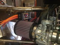
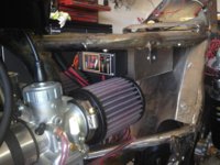
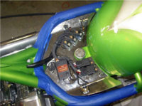
Well I finally got over moving and starting to get some work done on my street tracker project again. I mounted my SSPB from Jim on the front of my Omar's battery box for a clean location I do believe. I am working on getting all of my electrical and components confirmed and a wiring diagram completed. Jim has been more than helpful on all the electrical I want to do on my project and assisting me in achieving what I want to do with my project, keyless, alarm, ignition and more. I look for more cool stuff out of this guy trust me.
IMG_1845.jpg

IMG_1846.jpg
 
I added the VR115 regulator and RadioShack rectifier mod to my on going tracker project. Both wired accordingly with a 4 atc fuse holder block. Original starter relay, original switch gear, and needed wiring. Running a Shorei battery and 55'60 halogen headlight and 1157 taillight. Sell me. Why should I run your setup instead posplayr?
 
Dave, Jim I am sure will tell you the ALL benefits but we always know coolness is a factor also. One that is apparent is that a fuse replacement would net be necessary to get back on the road again after a fault.
 
I added the VR115 regulator and RadioShack rectifier mod to my on going tracker project. Both wired accordingly with a 4 atc fuse holder block. Original starter relay, original switch gear, and needed wiring. Running a Shorei battery and 55'60 halogen headlight and 1157 taillight. Sell me. Why should I run your setup instead posplayr?

Dave,

Even though you have tried to keep your electrical to a minimum, you can still benefit from the SSPB. After an install:

1.) There will be much less current running through both the Ignition switch and the Kill switch so you will have higher voltages to the coils for improved running (assuming it is too low in the first place). It will also stay that was even if your Ignition and Kill switch crud up as there is essentially very little current flowing through. This is equivalent to having an mechanical relay connected to both the IGN SW and Kill SW.

2.) Assuming electric start, you will have 5 more amps available for cranking because of the headlamp cutout. If you have kick start there is an easy modification to switch the headlamp off during start up. You need a switch through, but the switch doesn't flow any current at it is the same deal as item #1) above. This is equivalent to having two other relays, one to power coincident with the IGN and one to cut out the headlamp with the START button.

I recently ordered a 55 Watt HID to see what happens on start up. As long as it stays below about 12 amps or doesn't mind being limited to 12 amps all will be ok. It should drop to about 3-4 amps while running which is fine. The specs I have been reading typically show spikes to 6 amps during start up but I have not seen any data yet.

The SSPB will also run fine with any combination of Incandescent and LED lights.

3.) If you need to add another accessory, there is yet another solid state channel (equiv of a mechanical relay) that you can setup either to power from IGN or +12V switch or a GND switch.

4.) You don't have to ever change any fuses nor worry about a fuses corroding and shorting out the fuse box when they get hot.

5.) The SSPB delivers "Safe Power". Assuming you route all power through it, you can short wires indiscriminately and it will not blow a fuse. As soon as the shorts are removed full operation is restored without any power resets, breakers or anything else. When there is an over current you will get an audible warning and a flashing red LED until it is gone. The unswitched power has the same protection.

6.) The SSPB is designed with a triple layers or protection against conducted emissions. That means that any current spikes over about 24 volts get suppressed (shunted to ground) by the SSPB. It can handle +/- 100 volt spikes including reverse hook up to the battery. The ability to suppress those spikes means that anything in parallel to the SSPB (either on the input or the output is also protected in the same way. So any sensitive electronics such as R/R's (connected to the input) or Ignition systems (connected to the output) has the same protection.

6.) Apparently the XS650 and it's alternator have some type of voltage kick back when shutting off as evidenced by the 20 amp fuses as well as some of the XS650 owners observations. The SSPB will suppress those negative going pulses.

7.) If you need to add any power devices to your bike, the SSPB provides safe and low loss control of those circuits. (1 un-switched and 4 switched)

8.) If you need to control your power for such things as an Alarm, and you dont have an ECU disable, the SSPB provides an easy way to disable either the Entire SIGNAL Circuit or just the IGNITION circuits.

9.) I have pretty much ignored most of the technical design details about why the SSPB is a optimum power distribution solution using the reliability and flexibility of modern solid state automotive grade electronics, but that is also a reason.

The Bottom line is that , in a small and very robust form factor the SSPB becomes the foundation for our bike's electrical system. It is the foundation from which to run and add the various elements while being trouble free and reliable with virtually none of the problems associated with the original design.

Hope that helps.
 
Last edited:
There you have it Dave, from the engineer's perspective like I said Jim is here and committed to the improvements for the motorcyclist. I am not sure he sleeps if he does he is working on stuff in his sleep typical engineer. Thanks Jim :thumbsup:
 
Wow! That is a lot to absorb. Leaving for a week of snowmobiling, so I will read it all one night while relaxing. One question though, It looks like the whole shebang is still at the mercy of 1 main 20 amp fuse?
 
One question though, It looks like the whole shebang is still at the mercy of 1 main 20 amp fuse?


Two reasons,

The connection to the battery has to have an inline fuse because if there is ever a short attached to the battery you will get fire as the battery has what is called "low impedance" which means it can supply a lot of current without dropping its' voltage. Think arc welder.

The R/R must be connected to the battery to get proper battery charging so you can't get away without putting a fuse between the battery and the Rectifier. This is primarily in case a Rectifier diode shorts to ground. Adding the fuse is really the only safe way to go.

The down side is really not that bad. A 20 amp fuse is pretty robust and not subject to breakage as much as a smaller fuse; it just doesn't flex as much under vibration. Secondly it is inline so not rigidly mounted to anything which avoids the vibration stress of a more solidly mounted fusebox. All in all this setup is very safe and very reliable.
 
Last edited:
Another thing to consider, is that you should be able to avoid this type of wiring "configuration", all primary power distribution and the main switching is controlled in the SSPB. The result is much cleaner with everything yu see here being consolidated into a single SSPB unit.

I found this picture under this ebay add for Chopper/Bobber harnesses

http://www.ebay.ca/itm/Basic-Choppe...ccessories&hash=item338b2f2016&vxp=mtr&_uhb=1
 

Attachments

  • Generic Bobber Build Harness.jpg
    Generic Bobber Build Harness.jpg
    50.7 KB · Views: 250
Back
Top