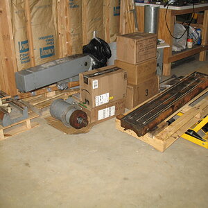
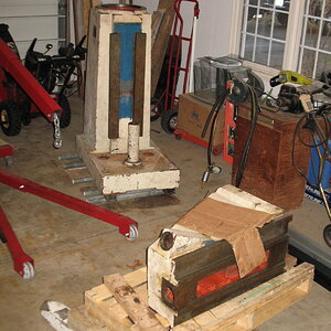
Supermax vertical mill renovation

This morning, I put the saddle on the knee and bolted on the guide plates.


After inserting the gibs, I found my next challenge. The gibs stick so far out the back of the saddle that the rear gib adjusters don't engage the threaded hole. There are two adjusters per gib in a push-me/pull-you arrangement, when they are both tightened the gib adjustment is locked in place.
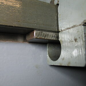
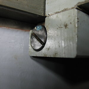

Both adjusters are supposed to be nearly flush like the second picture if the gib is the correct thickness and length. In order to get them into that range, I calculated that a shim of between 0.009" and 0.011" (depending on which of the three gibs) is required to get them into the correct position. I have 0.010" shim stock on order for pick-up tomorrow morning from my favorite hardware store.

The other thing I found is that half of the lube points for the one-shot lube system are on top of the saddle and UNDER the table. I was planning on putting the saddle on, followed by the table and THEN figuring out the lube lines but that won't work so I started looking into the lube system. Here's what I have to start with. The lube system came in a five-gallon bucket and appears to be all there. I say appears as I found another diagram in a different version of the manual and neither one matches exactly what I have but they are both close.
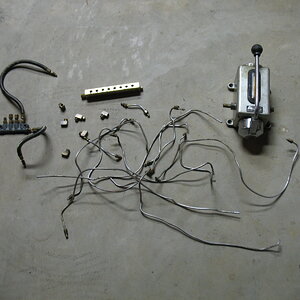
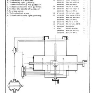

Since I was ordering shim stock from McMaster, I added a roll of 4mm nylon tubing and some compression sleeves in the hopes that I can use the pump (assuming it still works), the distribution blocks, meters and fittings and only have to replace the aluminum tubing with the nylon. Fingers crossed. At least I've ID'd all the lube points so that's something. Only one is left in question, one diagram shows two points on one end of the saddle and the other shows one on each end. My saddle has all three, so I'll have to figure out which ones I really need by checking all the drillings and see how they are interconnected.
 
Thanks RC4MAN.

I picked up the shim stock, 4mm tubing and compression sleeves this morning. I tried the tube and compression sleeve in one of the old fittings, but it was too long, and the threads wouldn't engage. Figures it couldn't be that easy... The sleeves have a collar and chamfer at both ends. I believe the idea is the collar enters the taper inside the fitting and crimps down onto the soft plastic tube to make a seal. It was only $20 for the sleeves and enough tubing to do two or three mills so not much of a risk to try shortening the sleeves in the lathe so they only seal on one end. They may not seal but there's only one way to find out.

The sleeves are only about 1/4" in diameter and 0.090" long in the middle where I chucked on them so not much to hold on to. I bought a Jacobs 59B headstock chuck years ago and cleaned it up and rebuilt and haven't found a use for it until today. The jaws are small and stick out from the body making it easier to adjust the sleeve to get it positioned just right. I used a drill bit, just a bit smaller than the sleeve ID, held in the tailstock drill chuck to help put the sleeves into the headstock chuck. It helped put them into the headstock straight and made setting how far in they were MUCH easier. I tightened the chuck by hand to avoid distorting the sleeve which also worked well.


It took me about an hour to do 30 sleeves, enough to do the whole lube system. I tried one and it seemed to tighten well and crimped down on the tubing so I'm hopeful they will work.

30164-8beffe0a51e626b57cd73269df25ec51.jpg


Next, I took the pump apart to see what kind of shape it's in. There was a sheet metal cup pressed over the end of the lever that had to come off by prying at four places on the edge and move it a fraction of an inch and working it slowly off. Underneath was the pump lever and cover and taking this off let the lube piston pop out.


The piston has some scratches in it, deep enough to feel with a fingernail so it may leak but, once again, only one way to find out. I polished the piston as smooth as I could get so fingers crossed it seals. If not, it looks like the pumps are about $40 so not the end of the world.

 
Last edited:
With the fitting thing "taken care of" (another spoiler) I started running all the lines to get things routed properly.


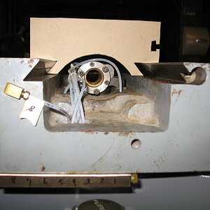
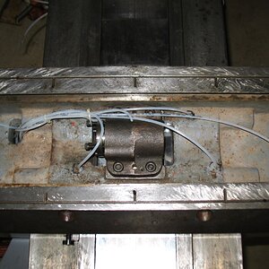
Once the table is on, there are no easy changes and I have to be careful that I don't rub against the bottom of the table or the leadscrew so I made a template of the bottom of the table to check that was well.


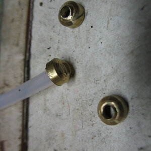
It looked good, so I pulled the junction block from under the saddle and started tightening all the lines using my new, handy dandy, modified compression sleeves. After snugging up about the fourth one, I started thinking they didn't feel quite right so I gave one a tug and it came right out! I pulled it out and this is what I found...


Comparing the internal drillings of the 90-degree fitting that DID compress well with the J-block it was obvious that there was no center drilling to let the hose protrude past the end of the sleeve, so it was compressing at the end of the tube AND the cavity was too deep so the nut wasn't fully compressing the sleeve before the nut threads bottomed on the top of the block! :mad: Sooo, I put the block in the drill press and set the depth stop to drill a hole slightly bigger than the OD of the tube and about 0.100" deep, which still left some meat in the bottom before breaking into the cross drill in the bottom of the block. I bought some more compression sleeves hoping they would be long enough to compress in the J-block, which they did BUT, the taper must not be suitable for smashing the little collar on the end as they didn't look as good as the one from the 90-deg. fitting. At least I couldn't pull them out and didn't have any better ideas, short of finding a more suitable J-block so I'm going to give them a shot, figuring it's 50/50 that they leak. I think I understand now why I found so much pipe dope on all the J-block fittings. Maybe I'll go down that road too (anybody asks, you didn't read that...) if they do leak. I'm thinking that the J-block is designed for putting metering blocks and/or adapters in and was never meant for compression fittings.


With the piping "complete" (we shall see) under the saddle, I could at least finish assembling the saddle. I then tried shimming the gibs, which worked but they now stick too far out the front side, but at least I now can figure out the correct shim based on the actual change in the position for each gib so that all the adjusters will be flush or nearly so, and I can continue with assembly.

 
Last edited:
Next step was to start assembling the table on top of the saddle. There was the usual massaging of dial parts to fit well on the leadscrew but no more so than usual. I thought this might be more difficult to get in position than the knee or saddle as the table has dovetail ways and has to be slid in from the end. I took my time rigging it and getting it level front to back and side to side using cam lock straps.


I have to say it went MUCH easier than I expected. From pulling it out to having it in position took maybe 20 minutes tops.


Which brings us to the end of major (read heavy stuff) assembly. Still plenty to do but nothing that requires the hoist. It's very satisfying to see the pile of parts gone and just a literal handful of odds and ends of hardware left over, some still required and some just extras. Now it's almost looking like a proper milling machine.
 
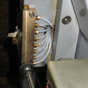
I got all the lube lines hooked up today and filled the pump with Vactra #2 way oil. The first couple pumps pushed a bunch of air out of the pump and lines and then it started pumping. I'm glad I went with the clear lines as it was easy to see where the oil was going and how fast. Amazingly, there were no leaks at any of the connections or at the pump. (Oh look, is that an Acorn I see!!) The only problem was that none of the lines with metering units, which is all the knee to base lube points, was flowing any oil to the fittings and one line wasn't flowing any oil at all. You can see it in the picture, it's the one furthest to the left in the J-block, zero oil in it. The others have some oil in them but it's not making it to the fittings.


The only thing I can figure is that either the metering units are partially plugged, I say partially as I checked them all with compressed air and they all flowed the same, or I tightened the gibs too tight and there is no place for the oil to go. These are the first tapered gibs I've ever used and I definitely tightened the knee a lot more than the saddle or table so the easiest thing to try will be resetting the gibs and see if it changes anything. On the plus side, all the pumping I did to try and get oil to the knee means the rest of the machine is awash in lube oil so I shouldn't have to lube anything for a year or so. I'm going to shim/re-shim all the gibs, get them set properly and then see what I can do with the knee oil. If it isn't the gibs then I'm going to play around with the metering units and see if I can open them up. I'd get rid of them altogether but then I would need new fittings which I'd rather avoid for now.
 
It's doable, they make adjustable distribution blocks, no idea what they cost. Before I go down that road I will see if I can get the original system to work properly. The thing I don't like about adjustable points is opening up one line takes flow from every other line since the volume and pressure are low and with 12 points that could add up to a lot of fiddling around. I'm still hoping that the original system was designed correctly and that it's just a matter of getting it to work as designed.
 
The mystery of the one knee line with no flow is solved. I put the meter in that line in backwards. There's a faint arrow stamped on the meters as they have a build-in check valve, so if they are installed backwards...no flow, guess I missed that one. Flipped it around and put a bolt in the spot where the hose feeds the other j-block so only the knee lines were getting oil and all four lines filled as soon as I started using the pump. The knee is the only set of ways with metering units, so it seems it is meant to have less volume than the other points which makes some sense as my impression (for what that's worth) is that the knee is used less than the saddle or table in general.

Guess I won't worry about it unless the knee ways start to run dry. I can always change the meters later with very little difficulty. The pump gives 8cc per stroke, which is about 1/4 oz. divided among 12 lube points, so no location gets a lot of oil in general.
 
Nothing to show but I re-shimmed the saddle and table gibs based on the results from my first try. This time it took three different shim sizes for the four gibs (0.004", 0.006" and 0.008") to get all the adjuster heads flush like they are supposed to be. This also allowed me to install the saddle wipers, which makes things look a little more complete.

After getting the gibs installed, I started adjusting them, starting with the table. I shifted the table all the way to the left and set the gibs fairly tight so that pushing and pulling on the left end of the table moved that end 0.001". Moving the table back to the center, the movement was 0.007" which shows the relative amount of wear in the ways. I have no idea if this is good or bad, if it causes any issues, I can always tighten the gibs at the expense of reducing the travel or at least making movement difficult and increasing wear of the ways and leadscrew nuts. At this point, I don't envision using all the travel but who knows, I'm new to all of this.
 
I can always tighten the gibs at the expense of reducing the travel or at least making movement difficult and increasing wear of the ways and leadscrew nuts.
That's basically what I did with my Atlas when I put it back together. Being 70+ yrs old, the bed and saddle were both worn. Based on the same logic as you, I figured 90% of what I'll do will be within 1-4 inches of the chuck. So i set the gibs so there's no play at 1" and about 5 thou out at 6". Yeah... they're worn that bad. Anyway, the gibs are pretty easy to get to on the Atlas, so I'll just readjust 'em if I need to go further out.
 
After adjusting the gibs, I adjusted the leadscrew backlash on the table and saddle. That was a total PAIN as the nuts are buried deep (as-in I could barely reach with the longest wrenches I have) under the table and the knee and required the adjusting and tightening of six allen bolts each. The knee was the worst because I couldn't reach it and see it at the same time so had to do the entire thing by feel. Eventually, I got both of them so that they had 0.005" backlash (the spec.) at the ends of travel where the screws aren't worn. In the worn areas in the center, the table had an additional 0.012" backlash and the saddle had an extra 0.007", not pristine but not horrible either and it won't mean anything when I install the DRO.

Next, I installed the scale for the turret and the rest of the metal tags. Originally, they were attached with drive rivets which made them a pain to remove for painting, so I put them back on with M3 button head screws, which required drilling and tapping 25 holes and opening up all the clearance holes in the tags. A little tedious but they will be a snap to remove for the next owner and they look good.


One tag was missing, the warning tag on the speed change wheel but HQT has it for around $7 so next time I'm up that way I will pick one up and add it. I'm pretty sure I can remember not to change speeds unless the motor is running until then. (plus it's not running now anyway...)

That only left installing the rubber chip guard to the column and saddle and the motor. The metal straps for the guard were bent up like many of the things on this machine so I straightened them, cleaned off 40 years of crud and reinstalled it, makes it look more complete and will keep most of the chips from getting into the back of the machine.

One chore I was looking forward to, was to take it off the wood blocks it's been on for hoist clearance and set it down on the floor. My son helped as it's so heavy now that I needed a 5ft. pry bar to lift it so he exchanged wood blocks as we lowered it in multiple 3/4" steps, one corner at a time until it was down. After a little shifting here and there to get it into its final position, and it was Bacardi time!

There was one more task to complete before I could install the final piece to this rather large jigsaw puzzle, the motor. It was missing the nameplate, so I had no way to know the horsepower or the running amperage, two very important pieces of information for purchasing and setting up the VFD. The issue was that my mill came with a 2hp motor standard and an optional 3hp motor. My friend's mill was virtually identical except being CNC and his 3hp motor DID still have the nameplate so by comparing winding resistance we figured out my motor is a 2hp. With that settled, I could now install the piece I've been looking for from the start of this project, after three months (almost to the day), the LAST piece!


I still need to get tooling and pick-out, install and set-up the VFD before making chips but, mechanically, it's D-O-N-E done! Woo-hoo! Tomorrow, I go to look at some tooling so I hope to pick up enough to get started, which will only leave the VFD, fingers crossed.


Quite a change from where this journey started...
 
Nope, definitely include me in that group too!

Today I went to look at the tooling and bought a vise, so I can check that one off my list.


And they were getting rid of all their HSS tooling and let me look through for anything I wanted before they scrapped it.


Some need sharpening, some look like they are useable, and some were unused. I only have 1/4" and 1/2" collets, but there are a few I can use now to get started. Another step closer...

VFD research ongoing...
 
Last edited:
That chips I smell a fryin' flyin'? :geek:
Sadly, not yet...

You have to understand, I don't like electrical stuff, know almost nothing about VFD's AND I took the silver medal in Men's Freestyle Procrastination at the 1988 Summer Olympic Games. (I still need to pick-up my medal...)

The mill needs two new electrical circuits (220V and 120V) run in the basement, VFD and controls researched, wired, programmed, etc. (Yuck!) While that proceeds at a snails pace, I've been working on the 80-year-old Kalamazoo bandsaw I bought a couple months ago. (much more fun!) I will need the mill to repair the half nut on the saw so that should give me some motivation to get the VFD installed.

The only reason the mill got done as fast as it did was...
a. I like mechanical stuff, and...
b. It was taking up half the garage and a quarter of the basement, so I was well motivated.

Normally, my post-retirement self would not proceed nearly that quickly.

Mikey, puleeze, you did a full renovation and you're not going to use a Kurt type vise :(
The vise I bought was cheap and will get me started while I look for a good deal on a Kurt. I can always sell it down the road but while I'm learning (remember, I have ZERO training and have never used a mill) it should do an adequate job while I practice launching steel chunks across the basement and embedding them in the walls.
 
Last edited:
Back
Top