Gas Cap Gauge for the early 70-73 Tank

TwoManyXS1Bs

BBQ Hunter
Top Contributor
Messages
14,670
Reaction score
15,296
Points
813
Location
Fredericksburg, Texas
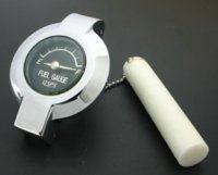
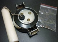
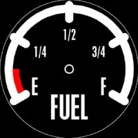
Another contraption I've been wanting for a long time, a gas cap gauge.

It's peanut's fault. He posted this awhile back, and it's been bugging me since.

http://www.xs650.com/threads/fuel-tank-sender-and-guage-mod.30035/

Then, there's this old classified that has a vintage Asahi gauge.

http://www.xs650.com/threads/asahi-gas-cap-fuel-gauge-nos.31356/

Some machines already have gas gauges, and then there's custom offerings from Asahi Denso and QSPS.

These use a plastic float, dangling from a chain.
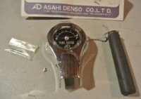
AsahiDenso.jpg QSPS-Gauge01.jpg QSPS-Gauge02.jpg

A very common utility type cap gauge uses a float on a spiral shaft, directly drives the needle.
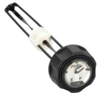
GeneratorGauge.jpg

The early 70-73 cas cap has a round/flat depression for the Yamaha tuning fork medallion. An ideal candidate for a fuel gauge.
 
For reasons known only to the demented, I chose to design a fuel sensor and gauge that's a bit different, working with these critera:

- NO permanent/irreversable mods to precious vintage parts.
- No electronics, mechanical only.
- No springs, the float sensor will push/pull the pointer.
- Completely adjustable, for needle range and offsets.
- A 240° needle sweep.
- Minimal height.
- Use glass instead of plastic crystal.
- Better precision than a dangling float.
- Senses the total fuel levels, about 8".

The float sensor is of a traditional design, a float swings up/down to track fuel levels. This happens in the left chamber of the tank, in this scheme:

XS1B-TankSketch01.jpg
 
Last edited:
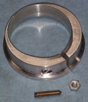
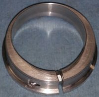
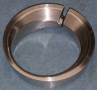
To get the float's swingarm pivot point down and forward from the tank opening, a positioning rod needs to be attached to the fill-neck, using a fill-neck adapter that expands and clamps to the inside of the fill-neck opening.

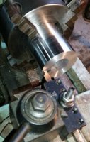
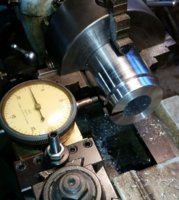
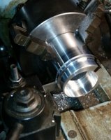
Starting with a 2" aluminum thick wall tube, in the 4-jaw chuck, turn the OD profile.
GCFG-NeckAdapter01.jpg GCFG-NeckAdapter02.jpg

Offset the work by 0.140".
GCFG-NeckAdapter03.jpg

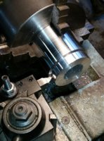
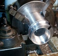
Bore the eccentric interior.
As large as possible, leaving the thick area at about 0.300".
GCFG-NeckAdapter04.jpg GCFG-NeckAdapter05.jpg

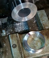
Part it off, about 0.500" wide.
GCFG-NeckAdapter06.jpg

Drill/tap the thick side for the expansion nut and stud.
Then slice, creating the expansion gap.
Install the nut and stud.
GCFG-NeckAdapter07.jpg GCFG-NeckAdapter08.jpg GCFG-NeckAdapter09.jpg

Work the edges, rounding and clearancing for the pivoting cas cap bottom.
 
Last edited:
A fixture is rigged-up, to hold the fill-neck adapter at a height of 8", simulating the tank depth. A cardboard/paper mockup is used to replicate the tank"s tunnel.
GCFG-Calibrate01.jpg


A rod is press fitted into a hole in the adapter, and bent to follow the tunnel curvature, creating the pivot point about 4" down and 3" forward.
GCFG-Calibrate02.jpg
 
As the float swings up/down, it's motion (and position) is delivered to the cap gauge by way of a push/pull cable. The cable is a 0.8mm (0.032") 7x7 flexible, housed in a 1mm (0.040") ID, 2mm (0.080") OD flexible PTFE sleeve. The PTFE sleeve is held in a double roll crimped 2mm ID brass tubing.

Made a double roll crimp wheel for use in a plumber's tubing cutter.
RollCrimpTubing2.jpg
RollCrimpTubing1.jpg


The PTFE sleeve has to be pushed into the crimped brass tubing, a few pounds of force. This crimp arrangement provides positive grip, and adjustability.
 
Last edited:
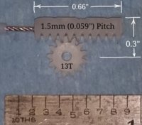
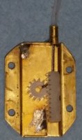
The other end of the push/pull cable is fitted into a gear drive rack, which will drive a small nylon gear that rotates the pointer.
GCFG-GearDrive03.jpg

This rack and gear system fits into a brass cover.
Another double roll crimped brass tube holds the cable sleeve.
GCFG-GearDrive05.jpg
 
Last edited:
I used a matching spare pointer from a salvaged XS1B instrument. It's driven by a 1/16" shaft, with a tapered end to hold the pointer.

It's a tricky, narrow 1.5° taper.
GCFG-PointerShaft01.jpg

GCFG-PointerShaft02.jpg
 
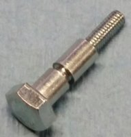
The original gas cap has a center post bolt that serves as the guide for the sealing gasket.
GCFG-Shaft01.jpg

This post/bolt is replaced with a slightly larger guide stud. The pointer shaft goes thru a 0.063" hole in the replacement center post.
GCFG-Shaft02.jpg


A 0.200" thick baseplate screws onto the new center post.
GCFG-GearDrive04.jpg
 
Instead of modifying my crusty ol' OEM gas cap, I acquired a new replacement from MikesXS.
MikesXS-Cap.jpg


This replacement gas cap is different from the OEM cap in that the circular medallion is a steel disc bonded within a flat recess, as compared to the OEM cap with a ring channel and 2 large retainer screws. This medallion must be pried out of the recess. A much better surface for the gauge faceplate.

Chuck up the new gas cap, get it centered.
GCFG-GasCap01.jpg


The original guide bolt has 4mm threads. The replacement guide stud uses 5mm threads. Drill/tap the gas cap for the 5mm threads.
GCFG-GasCap02.jpg


Reface the recess, take off about 0.020"-0.030", square up the recess edge.
GCFG-GasCap03.jpg
 
Acquired a 50mm domed pocketwatch crystal.
GCFG-BezelCrystal.jpg


Now, make its bezel.
Chuck up a 2.25" aluminium round, cut the basic OD and ID.
GCFG-Bezel01.jpg


Turn the outer profile. Bore the interior to 50mm, leaving the retention edge. The bore bit has a 15° back edge, to match the angle of the edge of the domed crystal, so that the retension ring has full contact with the glass, reducing stress breakage.
GCFG-Bezel02.jpg


Part off this trim ring (bezel) to the appropriate thickness.
GCFG-Bezel03.jpg


The trim ring (bezel) is fitted to the cas cap and (4) #0-80 screw holes are drilled and tapped.
GCFG-Bezel04.jpg


The crystal is fitted into this trim ring, retained by another thin ring (not shown) fitted to the bezel's ID.
 
only those who have patience to do simple things perfectly ever acquire the skill to do difficult things easily.

(someone famous must have said something like this.) love your project and all the talent you possess.
I am envious of your skills, something I daydream about ... but I do have one special skill making "excellent monkey noises"
 
The float sensor is calibrated for the bottom (empty) position.
GCFG-Calibrate02.jpg


And for the 8" (full) position.
GCFG-Calibrate03.jpg


For this particular setup, I need a total gear/rack travel of 0.520" to get the 240° pointer sweep. The float arm position can be adjusted at its pivot clamp to get the desired travel ratio. The sleeve ends can be moved in/out of their crimped tubes to establish the offset.
 
Last edited:
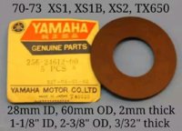
The rubber sealing gasket supplied with the new gas cap has a rather small 56mm OD, barely covers the tank opening. My old OEM tank gasket has a 60mm OD. Much better fit, and avoids potential leakage from damaged edges of a too-small gasket.
256-22612-00 OEM01.jpg

Making a replacement gasket. A 3"x3" piece of 2mm (or 5/32") neoprene sheet will be used. At $0.10 per sq-inch, that's $0.90. Make a washer of 60mm OD, washer of 28mm OD. These will be used as cutting guides. Use a hole size that's convenient (I used 3/8"), and punch this in the middle of the neoprene sheet. Make a wood backing plate with this hole.

Chuck a bolt (3/8") in the lathe, fit the backing plate, neoprene sheet, the larger washer, the smaller washer, nut. Run the lathe at low speed, run a tool up close to the cutting guide (washer), spritz a little WD-40 on there (great cutting lube for rubber), place an Xacto knife on the tool, alongside the cutting guide, and slowly plunge the knifepoint into the neoprene.
XS1B-GasCap-Gasket01.jpg


Keep the knife aligned with the cut direction.
Super slick trick, much easier than it looks.
XS1B-GasCap-Gasket02.jpg


Remove the trimmed-off outer sheet. Remove the nut, smaller washer, larger washer. Reinstall the smaller washer and nut. This is the cutting guide for the ID of the gasket. The results:
XS1B-GasCap-Gasket03.jpg


This new 60mm gasket is a better fit in the gas cap.
XS1B-GasCap-Gasket04.jpg
 
Back
Top