-
Enjoy XS650.com? Consider making a donation to help support the site.
XS650.com receives a small share of sales from some links on this page, but direct donations have a much greater impact on keeping this site going.
You are using an out of date browser. It may not display this or other websites correctly.
You should upgrade or use an alternative browser.
You should upgrade or use an alternative browser.
650performance
XS650 Addict
It depends upon how aggressive you want to be, Dale. If you are using a sticky DOT tire - like the Avon vintage racing tires - then even on the street you'll easily ground anything that's outside of the lower frame rails. Though dirt track frames are different, the bottom rails are essentially the same width as the stock frames.
So, with a Shell, Champion or C&J frame the pipes are placed below and positioned so the centerline of the each pipe is as high as possible next to the engine's sump and always inside the frame rails. TT pipes or high pipes are the safest choice because even if you are leaned over and hit a pot hole or dip (which further compresses the suspension) you still won't ground and lift the rear tire.
With your welding skills you can reroute the pipes so they are closer to the bike's centerline as they pass under the engine and then angle them outwards right around the area of the swingarm pivot (once again staying really tight against the frame) so they will be nicely positioned to mate up with the megs.
Good luck and kudos. Your project is really coming along nicely.
Thanks for your reply Craig, I'm having a look at it now and two options come to mind....
1. Drop 2" out of the vertical part of the header, this will make the pipe hug the bottom of the stator cover/foot peg area a lot more closely.
2. Get a set of Gary's underslung TT pipes at a later date...just had a look at cone eng's site. To get the bends I'll need it would be cheaper to get another set of headers.
Think I'll go with option 1 and see how they go....in the meantime I will get the other million jobs done on this thing.
BTW - got your guide that I printed as a shop manual out yesterday for the first time in 2 years, need to reaqaint myself with it.
[emoji111]
Before you cut those headers have you considered buying some pipe, bends and maybe a doughnut from an exhaust shop and making your own. That way you can route the pipes where you like and have the existing headers to sell.
It is time consuming but rewarding when they are done.
Learning from, and enjoying this thread a lot, thanks to all for contributing.
It is time consuming but rewarding when they are done.
Learning from, and enjoying this thread a lot, thanks to all for contributing.
Hi Signal, I have considered purchasing my own bends, probably need to get some pricing locally. Unfortunately I live in a small mining community at the moment and the nearest exhaust shop is about 1.30 Hrs drive from me.
Like I said above I'll give these a go first and see what happens.
Like I said above I'll give these a go first and see what happens.


goodgollyjosh
XS650 Addict
Looking Good!
Update - been getting some traction with this lately....

Recently got my 750/4 back together and have been wanting to get this xs engine finished for a long time....sometimes life just gets in the way.

Pulled the engine to disassemble completely, it had been too long for me to comfortably just assemble the top end.

As I had glass beaded the cases there was one thing I wanted to do but never got done, flush the main pressure gallery along the front of the engine (l/r) to confirm cleanliness.


As you can see there was remaining glass bead in the gearbox pressure feed gallery, recommended anyone bead blasting their cases have this done and the starter spigot removed and cleaned behind also.


The outboard rh crank bearing had developed a few marks from sitting for the last 2 years. I had greased the other bearings well and they had suffered no such damage - putting it down to lack of grease when packed away and being exposed on the outer end.

Cases were cleaned,washed,cleaned,washed then blown dry.

Reassembly


Shameless plug for Craig's guide


Ross pistons installed, starting to measuring squish clearances


Playing around with the head


O/s kpmi valves and springs

This is where I'm at today, unfortunately having issues with the 130-y r&d spring kit I purchased from Gary Hoo's.
I'll have to contact either Gary or r&d as you can plainly see the ti retainers have not been machined deep enough to allow full engagement of the locks as compared to the oem retainers and locks in the above photo.
Not sure how this happened...but I'm sure Gary or r&d will be able to help me to sort it out.
In the meantime I'll Continue to check valve/valve clearances as I'm running a shell #1 Cam and o/s valves with custom pistons, don't want things to get messy + get the bronze guides installed.
Recently got my 750/4 back together and have been wanting to get this xs engine finished for a long time....sometimes life just gets in the way.
Pulled the engine to disassemble completely, it had been too long for me to comfortably just assemble the top end.
As I had glass beaded the cases there was one thing I wanted to do but never got done, flush the main pressure gallery along the front of the engine (l/r) to confirm cleanliness.
As you can see there was remaining glass bead in the gearbox pressure feed gallery, recommended anyone bead blasting their cases have this done and the starter spigot removed and cleaned behind also.
The outboard rh crank bearing had developed a few marks from sitting for the last 2 years. I had greased the other bearings well and they had suffered no such damage - putting it down to lack of grease when packed away and being exposed on the outer end.
Cases were cleaned,washed,cleaned,washed then blown dry.
Reassembly
Shameless plug for Craig's guide
Ross pistons installed, starting to measuring squish clearances
Playing around with the head
O/s kpmi valves and springs
This is where I'm at today, unfortunately having issues with the 130-y r&d spring kit I purchased from Gary Hoo's.
I'll have to contact either Gary or r&d as you can plainly see the ti retainers have not been machined deep enough to allow full engagement of the locks as compared to the oem retainers and locks in the above photo.
Not sure how this happened...but I'm sure Gary or r&d will be able to help me to sort it out.
In the meantime I'll Continue to check valve/valve clearances as I'm running a shell #1 Cam and o/s valves with custom pistons, don't want things to get messy + get the bronze guides installed.
Last edited:
Update - both r&d and Gary responded within 24hrs.
Zach from r&d believes I have a set of 7mm conversion retainers instead of the standard 8mm ones, he is sending me the correct retainers to replace them.
So, a shout out to Gary Hoo's and R&D for their customer service and willingness to back their products.
Ciao
Zach from r&d believes I have a set of 7mm conversion retainers instead of the standard 8mm ones, he is sending me the correct retainers to replace them.
So, a shout out to Gary Hoo's and R&D for their customer service and willingness to back their products.
Ciao
Been progressing with setting up the cylinder head.
Results as follows -
Valve/valve clearance on overlap - both cylinders = 0.080" @ 0.006" & 0.012" lash
Copper head gasket thickness = 0.0575"
Base gasket = nil
Cam = Shell #1 regrind
Squish varies from 0.050" @ the edge of the piston crown, 0.0445" at the first angle of the dome and 0.022" at the last steeper angle of the piston crown. The 0.022" will be machined to be 0.035"
Tried the modelling clay...never again. Too messy and sticks to things when you don't want it too. It was back to the old faithful resin cored solder...


0.025" clearance = a bit tight

Measuring squish

Piston /valve clearance after 0.040" was taken from ex flycuts and Cam timing straight up running 0.006" and 0.012" lash.
#1in 0.0655"
#1 ex 0.065"
#2 in 0.066"
#2 ex 0.066"
Cam timing will more than likely be advanced 3-4° - opening up piston/ ex valve clearances a touch more.


Before and after


After getting a.t.f. everywhere C.R. has been calculated to be 9.65:1
Also took 0.003" from head surface to clean it up, it was not flat.

This where it sits now, waiting for ti retainers so valve spring heights can be set, then assembly.
Ciao

Results as follows -
Valve/valve clearance on overlap - both cylinders = 0.080" @ 0.006" & 0.012" lash
Copper head gasket thickness = 0.0575"
Base gasket = nil
Cam = Shell #1 regrind
Squish varies from 0.050" @ the edge of the piston crown, 0.0445" at the first angle of the dome and 0.022" at the last steeper angle of the piston crown. The 0.022" will be machined to be 0.035"
Tried the modelling clay...never again. Too messy and sticks to things when you don't want it too. It was back to the old faithful resin cored solder...
0.025" clearance = a bit tight
Measuring squish
Piston /valve clearance after 0.040" was taken from ex flycuts and Cam timing straight up running 0.006" and 0.012" lash.
#1in 0.0655"
#1 ex 0.065"
#2 in 0.066"
#2 ex 0.066"
Cam timing will more than likely be advanced 3-4° - opening up piston/ ex valve clearances a touch more.
Before and after
After getting a.t.f. everywhere C.R. has been calculated to be 9.65:1
Also took 0.003" from head surface to clean it up, it was not flat.
This where it sits now, waiting for ti retainers so valve spring heights can be set, then assembly.
Ciao
Last edited:
You've been quite busy. Looking good so far.
Long ago used a kind of plumber's putty that wasn't very sticky. Would roll up small BB-sized balls, spray some dry lube on surfaces, and place them wherever.
Was the camchain tunnel area the lowspot, or did you find some other types of lowspots?
...Tried the modelling clay...never again. Too messy and sticks to things when you don't want it too. It was back to the old faithful resin cored solder...
Long ago used a kind of plumber's putty that wasn't very sticky. Would roll up small BB-sized balls, spray some dry lube on surfaces, and place them wherever.
... Also took 0.003" from head surface to clean it up, it was not flat...
Was the camchain tunnel area the lowspot, or did you find some other types of lowspots?
Yes - around the centre of the head was low, all better now.You've been quite busy. Looking good so far.
Long ago used a kind of plumber's putty that wasn't very sticky. Would roll up small BB-sized balls, spray some dry lube on surfaces, and place them wherever.
Was the camchain tunnel area the lowspot, or did you find some other types of lowspots?
Have to say I think I love my lathe and mill....
Been very busy, I think this things been together about 8-10 times checking everything, the time it takes to do things correctly....but when running custom rods, custom pistons, larger valves and a higher lift cam things need to be "just so".
A bit more involved than throwing together your standard bore stocker...
Last edited:
Dale, what's your email address? I stumbled across an article that may be of interest to you.
That engine is taking shape and looking good!
That engine is taking shape and looking good!
Dale, After talking to Griz tonight about an E Bay sighting,I scored 4 Arias 80mm KZ 1000 pistons for 149.00 in excellent condition Bought a bunch of heads and motor parts from Griz also,so it's slowly coming together. Decided I was gonna deck the head to get the compression up if needed with the KZ's. All I need is a dome with 20ccs
Bought a bunch of heads and motor parts from Griz also,so it's slowly coming together. Decided I was gonna deck the head to get the compression up if needed with the KZ's. All I need is a dome with 20ccsGood to hear it's coming together Jack, my engine is built, just need to get the bike done now.....Dale, what's your email address? I stumbled across an article that may be of interest to you.
That engine is taking shape and looking good!
Regards,
Dale
Looking good
If you ever get an itch to explore in taking the xs ports to a newer level,give this article a good reading. It's doable but there are some limiting factors though. The XR ports where copied by Harley from a experimental 350 goldstar and the rest is history. That BSA is in your back yard and is bad ass,his name is Mark Parker.
http://www.accessnorton.com/norton-intake-ports-compared-harley-750-t16544.html
More progress, but not much....hmm.
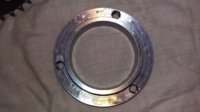
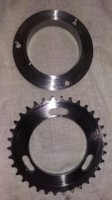
I made up a cam sprocket carrier to accommodate an adjustable cam sprocket, as I want to double check the valve spring seats this will be installed prior to start -up. The sprocket is just an OEM one thats been cut down, the carrier has been machined from high carbon steel and has a 0.001" interference fit (same as OEM). Adjustment allows +/-10 deg either way.
With full time study + working on my own FXR and other peoples Harley's ad-hoc, things are happening very slowly with this thing.....next update unknown.
Ciao.
Attachments
Thanks for posting the photos of the cam sprocket carrier. I also like your cartridge oil filter design.
It does take time to do things correctly, don't be discouraged you will get there keep plugging away.
It does take time to do things correctly, don't be discouraged you will get there keep plugging away.
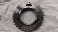
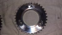
Cam sprocket V2.0
Couple of photos and and a short video of the setup.
After coming across two photos of Megacycles adjustable sprocket carrier online I decided to make my own.
+/- 10 degrees adjustment
Made from 4140 and has a 0.07mm (0.003") interference fit on the camshaft.
Shouldered grade 10 bolts are Yamaha - P/N 90105-07004 (from an FZR1000/FJ1100 I believe.?)
Over the next few weeks I will be drawing this carrier up in CAD
I have noticed there has been some photos disappear from this tread..? I don't know what has happened there..?