-
Enjoy XS650.com? Consider making a donation to help support the site.
XS650.com receives a small share of sales from some links on this page, but direct donations have a much greater impact on keeping this site going.
You are using an out of date browser. It may not display this or other websites correctly.
You should upgrade or use an alternative browser.
You should upgrade or use an alternative browser.

the top loop will be braced in at least 3 areas to take any forces upon it. will this take care of what you are thinking...or am i still lost in translation kop?
lost in the triangulation is more like it .
With out doing another thing raise the rear shock mounting three to four inches by changing the angle of the added brace on the swingarm . You'll see it eventually .
And when I do this kind of thing I replace the existing spring with something a lot softer so I can see it all work . I then reinstall the "real" spring and jump up and down on the thing with a fat chick already sitting on it ;-0 . So much for sophisticated testing ...
~kop
vernk
XS650 Addict

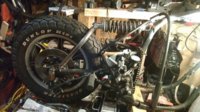
Roughly, i see the shock as to long and from where the brace is sitting the shock should be mounted to the frame about the bottom of the reinforcing on the bend.
If you visualize 3 points:
1 - The linkpin at the front of the shock.
2 - The linkpin at the rear of the shock.
3 - The swingarm pivot axis.
Then draw a line from 1 to 2, and another line from 2 to 3.
When these lines are perpendicular, you have max spring effectiveness.
When these lines are greater than 90°, you are in a 'falling' leverage zone.
When these lines form a straight line, you have entered 'overcenter', and the spring will lift the wheel...
vernk
XS650 Addict
i think i see. as kop said, raise the top tube thereby doing what you said: making that angle more acute. close the angle to 90 or less and bring the top of the shock lower at the bottom of the neck's reinforcement plate as skull said. should i scrap the monoshock i have? maybe i'll reuse the old shocks but put both side by side in place of the mono.
actually if i reuse the old shocks as they are shorter i can bring the top linkpin even lower on the frame's downtube, and keep the top tube of the swingarm brace around where it is now? or SHOULD i mount the top of the shock to the reinforced area?
actually if i reuse the old shocks as they are shorter i can bring the top linkpin even lower on the frame's downtube, and keep the top tube of the swingarm brace around where it is now? or SHOULD i mount the top of the shock to the reinforced area?
Attachments

vernk
XS650 Addict
8.5" ebay dirt bike/atv shock
10.4" ebay dirt bike shock
should i just stay away from these? figure these may be just too soft. this shock i have now does have some adjustment to it to go shorter. just don't have the spanner wrench. i'll have to order one.
10.4" ebay dirt bike shock
should i just stay away from these? figure these may be just too soft. this shock i have now does have some adjustment to it to go shorter. just don't have the spanner wrench. i'll have to order one.
The triangle you've drawn defines the action zone for the spring. Like a pair of scissors, it opens and closes. If both legs (left & right) are equal length, you'll get max spring effect. With different length legs, the leverage ratios change as the suspension moves, in a somewhat sinusoidal fashion. However, the spring rate is linear, increased force as the spring is compressed. The true reactive force is found by multiplying that sinusoidal leverage value with the spring force, thru all the suspension angles. By selecting appropriate leg lengths and spring rate, you can get an increasingly aggressive reactive force (stiff suspension), or a flatter reactive response curve, like the long-travel soft suspension of dirt bikes...
vernk
XS650 Addict
I got it. You're smart. Lost me at hello.
vernk
XS650 Addict
Would it be best if all three legs are equal in length? Or just the left and right
Left and right being equal will yield the stiffest, linear and most predictable suspension potential. Is that what you want?
Having the loop braced in the way you mentioned will yield an important benefit, the stiffening of the swingarm assembly, well worth it.
Also, this suspension now puts a lot of tensile force on the swingarm bushing, so may want to add grease fittings as necessary to keep it alive...
Having the loop braced in the way you mentioned will yield an important benefit, the stiffening of the swingarm assembly, well worth it.
Also, this suspension now puts a lot of tensile force on the swingarm bushing, so may want to add grease fittings as necessary to keep it alive...
To give you an idea of spring requirement, consider the length ratio (assuming those two legs in your diagram are equal).
Swingarm pivot point to axle is swingarm length.
Swingarm pivot point to rear shock linkpin is the belcrank leg length.
Swingarm length divided by belcrank leg length is the force multiplier.
Suppose swingarm is 20" and belcrank leg is 15". 20/15 (1 1/3) would be the force multiplier.
If your original dual shocks supported 200 lbs each, then you have a single shock spring trying to support 400 lbs times the force multiplier, 1 1/3, or about 530 lbs.
Sorry I can't give you specific answers, this is engineering methodology, teaching you to fish...
vernk
XS650 Addict
It has fittings from factory is that good enough?
It has fittings from factory is that good enough?
The factory fittings on the ends of the swingarm bolt will work if you're using the stock spiral-grooved bushings. If you're using the bronze bushings, best to add grease zerks to the swingarm. I believe 5Twins has an excellent pic here somewhere of that mod, I can't find it...
vernk
XS650 Addict
To give you an idea of spring requirement, consider the length ratio (assuming those two legs in your diagram are equal).
Swingarm pivot point to axle is swingarm length.
Swingarm pivot point to rear shock linkpin is the belcrank leg length.
Swingarm length divided by belcrank leg length is the force multiplier.
Suppose swingarm is 20" and belcrank leg is 15". 20/15 (1 1/3) would be the force multiplier.
If your original dual shocks supported 200 lbs each, then you have a single shock spring trying to support 400 lbs times the force multiplier, 1 1/3, or about 530 lbs.
Sorry I can't give you specific answers, this is engineering methodology, teaching you to fish...
I absolutely appreciate your help. May take me a bit to get it.
 . So do I need a spring rated for at least 530 lbs worth those numbers?
Well, I'm just guessing at those numbers, might be close enuff. Best way is for you to do the measurements and plug them into the raw formula. The idea here is to get a grasp of the geometries and forces involved so you can arrive at a working version. The selected shock may introduce mounting challenges, and knowing how to adjust the geometries and anticipate forces will allow you freedom in your design. Which is what many of these custom builds are, unique designs, each with their own challenges. There's likely a monoshock design in here that you could copy, but that assumes it was done correctly, and we'd like our members to be knowledgeable about what they're doing. We're all learning from this...
vernk
XS650 Addict
Oh no I realized those were only examples but I can apply the formula with my set up. I can figure a mount for the shock I wanted to ensure proper angles. I realize this shock isn't meant for this type of application but unless otherwise contraindicated I can figure a mount design. But regarding spring rate should the spring be able to handle that 530lbs alone or must I factor the weight of myself n passengers if any
Well, do the measurements of your design, find the force multiplier. As far as weight, you could guestimate, maybe 380 lb bike plus 170 lb rider gives 550 lb total. Then figure maybe a 30/70 weight distribution, 30% on front, 70% on rear. That gives 70% of 550 lbs is 385 lbs on rear wheel. Of course wheelies puts it all on the rear. Passengers add a little, too. So, figure a minimum of 385 lbs times your force multiplier to get starting point for your spring. Do the same for the other weights to determine final spring travel force. The difference between the two spring forces, and the travel desired of the spring, will give you a target spring rate (lbs/inch).
For example, if the spring must supply 550 lbs at normally seated ride height, and 800 lbs with passenger, not fully compressed, and the desired shock length change is, say, 2 inches, then the spring rate would be (800-550)/2, or about 125 lbs per inch. At that rate, the spring would need to be initially compressed about 4 1/2 inches to get the initial 550 lb force.
Again, this is just an example. Define your design geometry, measure, and see what you get. Sometimes, making side-view drawings, cutting out pieces, pinning parts to see the movements helps a lot.
vernk
XS650 Addict
will do. thanks! this weekend, hopefully will get some triangulation work done. i'll see what i can do with this shock since i have it....here's hoping