Programmable advance TCI Replacement

I can't get the "Bypass" function to operate. I get nothing at 250, 500 or 1000rpm. It's like the box isn't even powered up.
Right! There is a bug in "Bypass mode" it doesn't work in your boxes. Corrected in TCIv11r5c6
Thanks for pointing that out !
 
Had a chance to play with it a bit installed in the SG today. Here's what I got.

Electric Starting:
Iffy. Sometimes it starts relatively easy, sometimes not. One time I spun it for 5-10 seconds with no start. As soon as I released the starter button, it started. My guess is that as I released the button, one piston was coming up on compression, voltage recovered, it sparked and lit off. A one in a thousand event maybe? It did give me the "impression" that it's a low voltage problem though.
With the factory TCI box, this bike has always been a "touch the button" starter. I reconnected the factory box just to verify I still get instant starts.... I do. The best starts with the Transmic box never came close to that. I would call the quicker starts "acceptable", but never as quick as the factory box.

Idle:
It was smooth and indistinguishable from the factory box. Timing was also identical to the factory box. About 13-14°. Yes, I'm running slightly retarded from the books 15°

Revving:
Same problem as Larry initially had. Above 3000rpm it starts missing badly. I went back in and used the "modify" command so that this box exactly duplicates Larry's... line for line. No help. Still misses badly above 3000. That did retard the timing a tad more to about 11-12°. Other than that, no change.

Hunting/surging:
At about 2500rpm it would start a rhythmic hunt/surge from about 2400 to 2600rpm, at a frequency of about 1 1/2 to 2 times/sec. The timing light showed it was advancing and retarding in sync with the surge.

That's all I had time for today. Back down to the paint room.
 
Here are the final settings I used where it seemed to run best (kick starts every time), with pickup location at 63* (which seemed odd given the calcs made ) and where it seems to follow the factory TCI advance, but is slightly retarded. Idles just at the right idle hash mark @ 1,100 - 1,200. Full advance is right in the middle of drain groove. My bike is also a one hit start with the stock TCI. As far as reving above 3,000, make sure you have the next entry at line 24 (I put it at 7,500 and 30 advance), and also made sure rev limiter was set to 0 (off). Mine ran good and went freely above 3,000, no problem, even under load/riding conditions. I'll try the lower 4k resistor and larger capacitor next week, time willing. I'll also try hooking up a separate battery for the e-start that someone suggested.
Screenshot_20220909-152650_Brave.jpg
 
Just got back on the forum after a bit of a vacation ... read and skimmed through the posts. I'd like to offer a few comments. Some of the issues you are reporting, I have already experienced when I built my arduino TCI. I had issues with input circuitry not seeing the pickup pulses. The stock TCI input circuitry is very well designed and likely built around the characteristics of those pickups. The input transistors are biased on (just barely on)quiescently and when a negative pulse comes in they switch. Because they are using only the negative half of the input signal, all positive noise is eliminated. The circuitry also uses other filtering on the input signals. The input circuitry will also operate on a very low battery voltage... all the way down to 8 volts. On bench tests, I measured extremely weak signals being used by the stock TCI box... as low as -1.5 volts. In my initial prototypes, I wasn't to careful at which transistors I was using or how they were biased. My test jig was pumping out a very strong negative pulse, so it worked fine on the bench, but not so well in the real world. In the end I closely copied the stock circuitry and used equivalent transistor substitutes. I also modified my jig to output -1.5 v pulses. Everything works fine now. The fact that you are having to jiggle and modify the input circuitry to make it work doesn't bode well. It would be nice to see what is being used as a input device bjt or otherwise, but I don't think we will get to know that. As I said, the stock boxes are built for the stock pickup coils. You might be better off installing something appropriate to this device.
The stock TCIs use only negative pulses. Some of the circuitry timing is based on trailing edge, some on leading edge. 40 and 15 degrees BTDC are the times of those pulses. variations may occur due to the placement of the pickup module attached to frame.
The stock TCI seems to use the decay of one of the charging capacitors to determine when to energize the coil(dwell). In tests on the bench I noticed a huge variance in dwell. At really low rpms, such as when starting the bike, the coil is energized for most of the cycle. I find it interesting that the choices for dwell are just finite time selections. For my arduino tci, the dwell is a function of the rpm or time spent in one revolution. Not to say that set time periods won't work, I just find it curious.
The fact that you are having trouble starting the bike while using the starter is significant. What this is telling you is that the TCI box is having trouble running on a lower voltage. The stock TCI will run on very low voltages, but the ignition coil won't. I don't know where the problem is with your setup.
 
I plan on retesting with a 4k resistor and larger capacitor. Hopefully by next week. Dealing with funeral this week. Sucks.
 
Just so y'all know... I figured this was gonna be a pretty simple process. It's gonna take a little more work and I don't want to keep my bike down for an extended period. Especially coming up on the end of riding season. I'll be moving all this work over to the run stand.
We're on a delay, not a stoppage. Stay tuned.

Thinkin' out loud, maybe a hall effect sensor might be the better way to proceed
 
From Jim's scope snapshot https://www.xs650.com/attachments/1661824425101-png.223450/
the "magnet" inside the rotor seems to be 25° lenght according to the distance from the positive to the neg. wave.

sleddog83 said the stock TCI uses the negative wave.
So IF the neg half (trailing edge of the magnet) is at 40°, then the positive one (leading edge) is at 40+25=65° which is very close to what Larryl came out with...

In short: it's possible to use the negative pulse at 40° (stock TCI) or the positive one at 65° (Transmic TCI)
The advantage of the last is you are able to get more advance than 40° BTDC if wanted. It's better to do more then less.

My TCI uses discrete components for the input stage and I want it to be quite "universal".
As a result it cannot be super-sensitive for the XS without being saturated with a 50Vcc pickup !
It still is sensitive: +1.7 to +2v for the pickup to be detected, but the voltage is lower with this big air-gap, hence the bias voltage.
Right sleddog83, it's much simpler to build the TCI around the pickup(s)
Something doable....

About the dwell time, fixed time is mandatory for new ignition coils with low impedance.
The dwell On 1/3 of the period in a point heritage. They had no other choice than doing that way, back in time..

>The stock TCI will run on very low voltages, but the ignition coil won't.
Interresting too! The coil MAY need of longer dwell with e-starter. That's why I asked Jim to test with 6ms, with no luck...
 

Attachments

  • pn.jpg
    pn.jpg
    11.4 KB · Views: 47
Last edited:
So for a true universal XS system; Drill, install a raised iron pin in the rotor, find a hall effect sensor that can be mounted to the stator?

More thinking out loud; is there enough room for dwell if two pins were used to create an ignition for a 277 crank?
 
The ~.080" air gap is quite large compared to most applications. Spitballing: If a conductive adhesive could be found a .060" wafer could be glued to existing pick-up coil - it's stationary rather than whirring around on the rotor:shrug:
 
The ~.080" air gap is quite large compared to most applications. Spitballing: If a conductive adhesive could be found a .060" wafer could be glued to existing pick-up coil - it's stationary rather than whirring around on the rotor:shrug:
My XS is points, so I have never seen a TCI setup. But is there no other way, like modifying stator housing and/ or TCI sensor to reduce the air gap?
 
Could one use a zenor diode to lop off excess voltage from the stock TCI pickups?
That would keep low RPM voltage up where it needs to be.
 
So IF the neg half (trailing edge of the magnet) is at 40°, then the positive one (leading edge) is at 40+25=65° which is very close to what Larryl came out with...
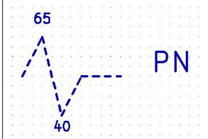
I don't think this is a correct interpretation or I am missing something here. Assuming the positive swing is the leading edge and the negative swing is the trailing edge. There is one magnet and two pickup coils separated by 25 degrees. One pickup has a trailing edge at 40 deg, one has a trailing edge at 15 deg. Where the positive edges show up in the rotation, I am not certain. Could be 42 and 17 or 44 and 19. But I don't think the positive edge is 25 degrees in front of the negative edge.
Of course these general numbers depend also on where the pickup module is placed on the stator frame. There could be a one or two degree variation in the degrees , based on how it is bolted to the frame. This is of course one of the ways of adjusting the stock TCI, ...adjusting where it sits in the stator frame. You could lower the idle advance to say 38 deg, but the high end will always be 25 degrees plus whatever you set it at at the low end.
 
You are right, I considered there was only one pickup and forgot there are 2 of them and the TCI uses the positive wave of each.

In the meantime, I redrew a TCI for XS650 with another input stage much more sensitive using a VR conditioner so it should be able to see the pickup even with less then 1v.
I'll make 5 of them and on the very first prototype I'll let the USB cable in place so the beta tester will be able to reprogram it if needed.
Question: who feels like capable of doing this? Gary ? :)
(To install a driver on a windows PC, connect the TCI, find the new serial port under "device Manager" in run a software)
 
Jim got us a long way in establishing the stock air-gap and the air gap the Transmic needed and one work-around. The other outstanding issue appears to be the electric start issue; did anyone get a voltage reading on the R/W and the W/R while cranking?
 
Back
Top