Hi all,
I am a newbie at this and never done any major engine work.
I figured I would do a write up cause it may help somebody else (newbie).
The idea is to fix a bike I purchaseda couple of weeks ago, I bought it off the PO with the knowledge of a problem in the gearbox.
He said he was having trouble with second gear so he took the bike to the local Yammy dealer.
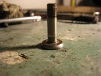
They found a small piece of metal stuck to the drain bolt, they guessed it was a piece of a gear and without taken engine apart they could not tell.
He took it home and never drove it till he sold it to me.
So......
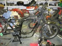
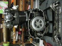
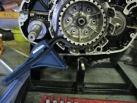
Take the engine out!
Pic 1 and 2
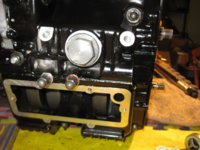
Remove crankcase cover of the alternator, remove drive sprocket, chain guard, undo two long screws on the alternator then carefully unclip wires from crank case.
Then remove strator.
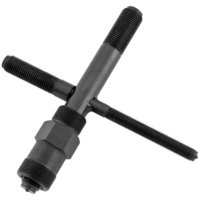
You will need a flywheel puller for the rotor off do not order this tool.!!!
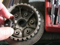
Pic 3
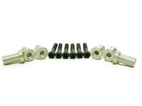
you need a special coupler nut which is not easy to come by.
the tool you need is part # 35-0040
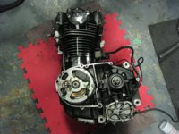
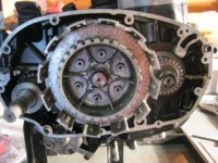
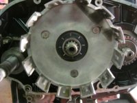
So now you work on the primary drive cover, even thoug oil is drained you will get oil coming out when you crack into the primary, put some rags down (I think somebody on here said diapers work great)
Remove oil filter housing first then remove the case.
Pic 4
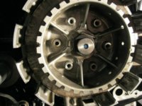
Remove clutch bolts ,springs and washers, they can be a bitch so use a impact!
Pic 5
Remove pressure plates, keep in the same order!
them remove mushroom head clutch pushrod, the bearing ( with a magnet ) and the main pushrod.
Pic 6
Question , should the mushroom pushrod have a mark like this?
pic 7
Ok so I have an issue with putting money out for a tool that is a old part off a clutch with two pieces of metal welded to them! (probably cause I didnt have an old clutch plate either,lol) so I though about a strap wrench, it worked like a charm, was only 10 bucks and I can use it for other things not just a clutch of a yammy!
pic 8
Remove lock nut on clutch and pull off clutch center,thrust plate, bearing.
Pic 9
Then clutch drum, bearing sleeve and washer, all to be kept in the same order, very important! (zipty thru the center works)
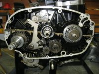
Pic 10
Now to start with the gearchange, pinion and kickstart removal.
pic 11
anybody know how to insert pics right in the paragraph? so I do not have to number them.
I am a newbie at this and never done any major engine work.
I figured I would do a write up cause it may help somebody else (newbie).
The idea is to fix a bike I purchaseda couple of weeks ago, I bought it off the PO with the knowledge of a problem in the gearbox.
He said he was having trouble with second gear so he took the bike to the local Yammy dealer.
They found a small piece of metal stuck to the drain bolt, they guessed it was a piece of a gear and without taken engine apart they could not tell.
He took it home and never drove it till he sold it to me.
So......
Take the engine out!
Pic 1 and 2
Remove crankcase cover of the alternator, remove drive sprocket, chain guard, undo two long screws on the alternator then carefully unclip wires from crank case.
Then remove strator.
You will need a flywheel puller for the rotor off do not order this tool.!!!
Pic 3
you need a special coupler nut which is not easy to come by.
the tool you need is part # 35-0040
So now you work on the primary drive cover, even thoug oil is drained you will get oil coming out when you crack into the primary, put some rags down (I think somebody on here said diapers work great)
Remove oil filter housing first then remove the case.
Pic 4
Remove clutch bolts ,springs and washers, they can be a bitch so use a impact!
Pic 5
Remove pressure plates, keep in the same order!
them remove mushroom head clutch pushrod, the bearing ( with a magnet ) and the main pushrod.
Pic 6
Question , should the mushroom pushrod have a mark like this?
pic 7
Ok so I have an issue with putting money out for a tool that is a old part off a clutch with two pieces of metal welded to them! (probably cause I didnt have an old clutch plate either,lol) so I though about a strap wrench, it worked like a charm, was only 10 bucks and I can use it for other things not just a clutch of a yammy!
pic 8
Remove lock nut on clutch and pull off clutch center,thrust plate, bearing.
Pic 9
Then clutch drum, bearing sleeve and washer, all to be kept in the same order, very important! (zipty thru the center works)
Pic 10
Now to start with the gearchange, pinion and kickstart removal.
pic 11
anybody know how to insert pics right in the paragraph? so I do not have to number them.
Attachments
-
 IMG_0224.jpg292.9 KB · Views: 311
 -
 IMG_0225.jpg250.6 KB · Views: 284
 -
 2011-Bikemaster-Flywheel-Puller---.jpg49.9 KB · Views: 250
 -
 IMG_0236.jpg254.9 KB · Views: 257
 -
 IMG_0237.jpg239.7 KB · Views: 271
 -
 IMG_0238.jpg173.5 KB · Views: 312
 -
 IMG_0239.jpg148.8 KB · Views: 313
 -
 IMG_0241.jpg231.9 KB · Views: 275
 -
 IMG_0242.jpg157.5 KB · Views: 310
 -
 IMG_0243.jpg199.6 KB · Views: 302
 -
 IMG_0245.jpg248 KB · Views: 669