About 77 kg.Out of curiosity has anyone ever weighed,or know the weight of the assembled engine,give or take a couple of kilo's??
-
Enjoy XS650.com? Consider making a donation to help support the site.
XS650.com receives a small share of sales from some links on this page, but direct donations have a much greater impact on keeping this site going.
You are using an out of date browser. It may not display this or other websites correctly.
You should upgrade or use an alternative browser.
You should upgrade or use an alternative browser.
Flat track project
- Thread starter Pipes
- Start date
Thanks guys,
Ok,I will try not to drivvle on lol...
Yes I am a welder although not as professional as some like you see on Instagram but I get byWhat you see is seamless cro-moly tubing for the all but the swingarm which is plain carbon steel TIG welded with appropriate wire and then capped with bronze just for asthetics as I plan to clear laquer the frame.
The rear mono shock uses a Yamaha R6 shock.The spring rate may be a head scratcher when it comes to it but as long as I give a supplier the approriate details they should be able to fix me up with a workable solution.I did think about twin shocks initially but I wanted to do something not necessarily more complex but more outside of the box.I purchased a YZ400F alloy swingarm with plans to use that but the more I saw it in the tubular frame the more I thought it would look out of place.I ended up fabricating a steel tube arm.Then the suspension.This came in the form of a monoshock either mounted as you see it or under the engine like a Buell,afterall if I was going to build something from the ground up then go all out...Then it dawned on me that the extent of the Buell idea would require some very clever engineering to make it look neat and still work efficiently and I got cold feet.Keep It Simple Stupid was in the back of my mind and while I could have mono shocked it from the swingarm straight to the frames backbone,cantilever style, I thought this idea a bit of a cop-out so I ended up with what you see.
The R6 shock is compressed with a linkage just as it is on the Superbike all be it with slightly different dimensions.I do have a short video I took somewhere of the shock (spring removed) being compressed by the linkage and in theory it should work fine.I still have room for adjustment with multiple mounting points for the linkage rods and other alloy linkage plates with differing hole spacings to change the ratio of lift etc...To be honest I spent hours on the net looking at animated shock linkage diagrams to get my head around how they work before I fabricated anything.I always like to do homework as I hate wasting money.The drawback this brings is the squeeze to get it all in there without extending the wheelbase too much.In fact I have gained about 50mm in length if I have my calculations right!!!
Lastly,you are correct in thinking MaxPete that I am using the engine as a stressed member.I am using all the engines mounts to hang it.One of the big conditions was to make the lovely looking engine a focal point....
View attachment 166561
Thinking out loud
That brown strut looks weak . ( even though 2 of them )
Assuming the bike weighs 250 kg --- half of it back
When moving the swing up and down there is a rotating point at the engine ..the vertical force ( perpendicular to swing ) in the brown 4 - 5 times the load on the wheel point of the swing
And since the strut is sitting in an angle the total force in it is larger.
Apologize if I have not read good enough or not understood the picture or sketch or measurements
And if this is a proven working setup.
But my first spontaneous hunch would be bigger dimension there than the swing
as it looks in the picture it is smaller
If you like and it is not done already you can put up more like a drawing perhaps someone can calculate a little as to forces
Hi Jan P ..
When you say 'brown' strut are you referring to the top mount??...if so I know what you mean.The mount has been welded since this photo including a plate over the top tying both sides together...There is always the option of placing a vertical gusset on top to increase stiffness perhaps?
.jpg")
When you say 'brown' strut are you referring to the top mount??...if so I know what you mean.The mount has been welded since this photo including a plate over the top tying both sides together...There is always the option of placing a vertical gusset on top to increase stiffness perhaps?
Hi Jan P ..
When you say 'brown' strut are you referring to the top mount??...if so I know what you mean.The mount has been welded since this photo including a plate over the top tying both sides together...There is always the option of placing a vertical gusset on top to increase stiffness perhaps?
View attachment 180541
At # 3 posting lowest picture 6 o clock
the strut in ca 45 degrees
# 15 posting the brown there in the moving picture
Just a feeling , without measurements and pictures ---- take it for what it is worth
Oh ok...the threaded bar connecting the linkage to the swingarm.In the UK we sometimes refer to them as 'dog bones' due to there shape.
Yeh those are just used for mock up and I now have some solid stainless steel bars turned up to suit the rose joint bearings.These are slightly bigger than the ones in the pic but I will take your advice into consideration.I may make some beefier ones,after all,I wouldn't want those to fail
_LI.jpg")
Yeh those are just used for mock up and I now have some solid stainless steel bars turned up to suit the rose joint bearings.These are slightly bigger than the ones in the pic but I will take your advice into consideration.I may make some beefier ones,after all,I wouldn't want those to fail
Last edited:
Well,that's xmas over and done with for another year..I hope you all had a good one and stayed safe 
Today I popped to my workplace to do some more to the bike.We are all off for a week so it's nice and quiet and I have the place to myself.
My new tyres arrived a few days ago so yesterday I fitted them to the new rims,very carefully I might add and fitted them to the frame.This is the first time the frame has been out of the jig properly and standing on its own two feet,or wheels in this case...
I had already made some spacers to take up the gap between the supplied bearing spacers and the fork leg and swingarm ends.It turns out the wheels do not sit central in the frame so I will have to re-measure and make new.
Before fitting the wheels I had to redesign the lower bearing tube which supports the suspension linkage as my original concept was a bronze bush but after giving it some thought I changed to a needle roller/bush set-up to match how the lower shock eye is designed.It will work much better but just requires more accurate fabrication.I machined a temporary alloy 'bush' while I am working on the bike so I do not commit to fitting the new needle bearings before getting the frame lacquered/painted.
Once the suspension was fitted,along with beefier link bars,I put the wheels in with the new spindles/axles.These new stainless spindles were made by a local firm as I wasn't confident in doing it myself on my little lathe and they could do a better job of the threads too.The rear spindle has threads both ends held on by two stainless steel nuts which I turned down a little and drilled them to give them a different look and applied a little heat to turn them a nice dull gold.Both spindles fitted the bearings a treat which was good as they cost me a lot more than I had planned,I am trying to build this bike on a budget afterall....
I also took a pic of the yokes after getting them blasted and to be fair I am happy with the coarse finish giving them a sandcast look.
I took some pics of the rolling chassis before the seat and tank were fitted and I am happy how it's going.The tank seems to suit it even more now which has always been in the back of my mind as to whether to use it or not but I think its going to stay now.
Oh ok...the threaded bar connecting the linkage to the swingarm.In the UK we sometimes refer to them as 'dog bones' due to there shape.
Yeh those are just used for mock up and I now have some solid stainless steel bars turned up to suit the rose joint bearings.These are slightly bigger than the ones in the pic but I will take your advice into consideration.I may make some beefier ones,after all,I wouldn't want those to fail
View attachment 180555
That looks a bit lightly constructed to me I'm afraid.
In particular, if those Heim joints are 1/4-28UNF - then they are only rated for about 2700 lbf static (see the attached document below).
I don't know the details of your suspension geometry but I'd bet it will generate a lot higher loads than that - particularly when it is working hard on a bumpy road.
Pete
Attachments
Maybe you're right but I reckon the rose joints should hold up...one of my other bikes (Suzuki) has links just like these and that thing weighs a ton and has a much longer swingarm,...if for any reason they do not hold up then they can be changed.Bigger bikes have been using them for years.(The second pic is generic,not mine)
.jpg")

...if for any reason they do not hold up then they can be changed.Bigger bikes have been using them for years.(The second pic is generic,not mine) Okey doke.
Do not get me wrong,I appreciate any advice given...Everyday is a school day...looking at the data on rod ends the aircraft type seem to be the more suited to the application.I shall do some research 
It seems steel on steel rod ends are much better dealing with shock loads...I have steel on bronze at the moment.
It seems steel on steel rod ends are much better dealing with shock loads...I have steel on bronze at the moment.
Last edited:
Well,that's xmas over and done with for another year..I hope you all had a good one and stayed safe
Today I popped to my workplace to do some more to the bike.We are all off for a week so it's nice and quiet and I have the place to myself.
My new tyres arrived a few days ago so yesterday I fitted them to the new rims,very carefully I might add and fitted them to the frame.This is the first time the frame has been out of the jig properly and standing on its own two feet,or wheels in this case...
I had already made some spacers to take up the gap between the supplied bearing spacers and the fork leg and swingarm ends.It turns out the wheels do not sit central in the frame so I will have to re-measure and make new.
Before fitting the wheels I had to redesign the lower bearing tube which supports the suspension linkage as my original concept was a bronze bush but after giving it some thought I changed to a needle roller/bush set-up to match how the lower shock eye is designed.It will work much better but just requires more accurate fabrication.I machined a temporary alloy 'bush' while I am working on the bike so I do not commit to fitting the new needle bearings before getting the frame lacquered/painted.
Once the suspension was fitted,along with beefier link bars,I put the wheels in with the new spindles/axles.These new stainless spindles were made by a local firm as I wasn't confident in doing it myself on my little lathe and they could do a better job of the threads too.The rear spindle has threads both ends held on by two stainless steel nuts which I turned down a little and drilled them to give them a different look and applied a little heat to turn them a nice dull gold.Both spindles fitted the bearings a treat which was good as they cost me a lot more than I had planned,I am trying to build this bike on a budget afterall....
I also took a pic of the yokes after getting them blasted and to be fair I am happy with the coarse finish giving them a sandcast look.
I took some pics of the rolling chassis before the seat and tank were fitted and I am happy how it's going.The tank seems to suit it even more now which has always been in the back of my mind as to whether to use it or not but I think its going to stay now.
View attachment 181431 View attachment 181432 View attachment 181433 View attachment 181434 View attachment 181435 View attachment 181436 View attachment 181437 View attachment 181438 View attachment 181439
I like your style in terms of friendly openness ...by the work you do it is evident that you are very competent.
And not many can that better.
Something that perhaps is worth consider .. If not already done ... bare with me if it is already analyzed
I have googled a bit on Frames
Usually the front has 2 downwards tubes or an extension out from a center vertical plane
A flat track example --Frame.jpg
XS650 --> XS650
Honda -->CBR


At least this gives a greater transversal stiffness ( If you put the frame on its side on two blocks and step on it in the middle )
There are some single tube fronts perhaps mostly hard tail which I believe seldom are driven hard
There exists a few flat track bikes with one front tube. Then by the looks of it a little larger diameter.
Material as wells as tube wall thickness affects .And this can already have been analyzed
I don't think the XS 650 frame are extremely solid.
It also comes down to styling preferences and expected driving style. Take this for what it is Worth
If I am being totally honest I have only researched information on frames through the net and a Tony Foale book I once owned.I wouldn't say I am making it up as I am going along but then again it does have little bit of 'lets see how this goes'
The frame you see is based largely on the Mule XS's which are quite similar ( I believe Mule have posted on here before) although they do have a different arrangement for the swingarm mount.I went for this look because I thought it very unique.As for the monoshock this was chosen again to be different and have some degree of engineering thought gone into it even though it was more of a challenge than twin shocks...I guess the key word in building conventional bikes is just that..'conventional'...I have built various bikes/cars but where I have done the engine on one I have modified the frame on another but only to a point.This build I thought I would do as much as everything as I could.I have never built a frame from scratch and thought 'what the hell'...


The engine is being used as a stressed member I suppose just like my 1995 Ducati I once owned for many years.That bike literally had everything bolted to the engine and had no undercarriage framework yet Ducati got it right as it handled impeccably but then again they have had years of research as success with it.
This doesn't mean mine will work...it may be a total failure but I hope not.The bike isn't going to be raced,only road ridden and it won't be abused.

I guess I could fit lower frame rails to increase some stiffness but I really want to keep the single down tube as it is but if i really need to then so be it.Again I appreciate all advice if you guys have any...I am always open to suggestions even if I do not take some of them.I am by no means an expert and there are far more intellectual people out there than me ...Cheers
The frame you see is based largely on the Mule XS's which are quite similar ( I believe Mule have posted on here before) although they do have a different arrangement for the swingarm mount.I went for this look because I thought it very unique.As for the monoshock this was chosen again to be different and have some degree of engineering thought gone into it even though it was more of a challenge than twin shocks...I guess the key word in building conventional bikes is just that..'conventional'...I have built various bikes/cars but where I have done the engine on one I have modified the frame on another but only to a point.This build I thought I would do as much as everything as I could.I have never built a frame from scratch and thought 'what the hell'...
The engine is being used as a stressed member I suppose just like my 1995 Ducati I once owned for many years.That bike literally had everything bolted to the engine and had no undercarriage framework yet Ducati got it right as it handled impeccably but then again they have had years of research as success with it.
This doesn't mean mine will work...it may be a total failure but I hope not.The bike isn't going to be raced,only road ridden and it won't be abused.
I guess I could fit lower frame rails to increase some stiffness but I really want to keep the single down tube as it is but if i really need to then so be it.Again I appreciate all advice if you guys have any...I am always open to suggestions even if I do not take some of them.I am by no means an expert and there are far more intellectual people out there than me
...Cheers I must try harder to post on time
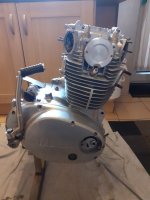
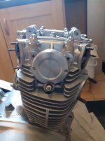
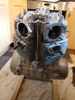
Anyway...weekend just passed saw me assembling the engine with the new 750 kit from Heiden Tuning.It went together really well and I am impressed with the quality of the barrels.Along with the kit went a new timing chain and tensioner guides.
The only mishap I had was a fault on my behalf but when I turned the crank to tdc both pistons raised ok but a little while later I needed to turn the crank some more and only one piston went down......my surprise was quickly followed by a forehead slap moment as I realised I must have missed the con rod hole as I pushed the wrist pin through (story of my life)...I had a little giggle then corrected my mistake.
I did get around to putting the head and chain on but it seems the engine is missing a couple of dowels so the torque down will have to wait till the new dowels arrive for the rocker box.
While I am waiting I took some advice from the forum and strengthened the lower sump filter too.
One step nearer.


Anyway...weekend just passed saw me assembling the engine with the new 750 kit from Heiden Tuning.It went together really well and I am impressed with the quality of the barrels.Along with the kit went a new timing chain and tensioner guides.
The only mishap I had was a fault on my behalf but when I turned the crank to tdc both pistons raised ok but a little while later I needed to turn the crank some more and only one piston went down...
...my surprise was quickly followed by a forehead slap moment as I realised I must have missed the con rod hole as I pushed the wrist pin through (story of my life)...I had a little giggle then corrected my mistake.I did get around to putting the head and chain on but it seems the engine is missing a couple of dowels so the torque down will have to wait till the new dowels arrive for the rocker box.
While I am waiting I took some advice from the forum and strengthened the lower sump filter too.
One step nearer.
Impressing
Not sure what is right or wrong but I am a bit old school with oil.
Rather to much than too little
At this point in time I would keep oil in the cylinders .
On top of the pistons.
Someone surely will correct if that is wrong.
Not sure what is right or wrong but I am a bit old school with oil.
Rather to much than too little
At this point in time I would keep oil in the cylinders .
On top of the pistons.
Someone surely will correct if that is wrong.
durgam_K
XS650 Addict
I love the mono shock.... I believe I will be going that direction on my next build.....
Keep it up.
Keep it up.
Loving this build.
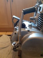
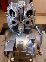
Ok,so today I managed to finish the top end,getting the thing torque up,valves adjusted etc etc..I have at last received the final clutch shim after 2 months of waiting and put that all together.I am going to make some new plate fasteners as the original screw heads are not in the best shape.
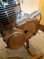
I now can take a measurement and shorten the actuator rod seen sticking out of the drive side casing for the slave cylinder,then I can look at making some exhaust mounting flanges like the inlets.
I also trial fitted the stainless steel kickstarter I made and it works a treat and it still uses the original shaft mount and plunger.
To match the alloy cover I made for the stator case I fabbed up a couple of cam covers which fit nicely but just need a little tweak around the sparkpugs.All the big things the engine needs to be almost ready is the ignition and carburation when funds allow.
Attachments
Last edited:
Similar threads
- Replies
- 4
- Views
- 1K