inxs

xx
Messages
2,268
Reaction score
135
Points
63
note...this is part 1 of a 5 part summary that i put together in order to understand a little about XS650 clutches...i have used photos in this series that i found on the net as well as my own - if anyone recognises theirs let me know and i will post credit for it - all accept my thanx for the use of...the information here is not what i would call complete so please if you read this and disagree, have some info that will extend this, or comments, post them... lets see if my experiment with attachments works...well i see it wasnt quite successful but ......

1. Yamaha, the timeline:


Well, I don't know much about clutches but nevertheless here goes.

In the beginning there was light, hot burning searing endless light and then god made bikes, in all concievable sizes and shapes and there was joy for noone, as noonne was there and he could choose endlessly between them.

Problem is all he knew about clutching was how to grab his balls trying to stop them falling through the sun during one of those oh oh WTF moments. Just as well there were so many bikes. Trouble was not only were some nicer than others to ride but eventually it became difficult to find one that worked properly.

Damn! Time to bend my head around shit.

Take the XS650 – basically 3 different clutch set-ups

The clutch was always a weakness. It never really handled the power, requires close monitoring. There are common complaints wrt engaging gears, slipping, oil sensitivity, neutral finding, sticky clutch and adjustment issues. The clutch engages quickly and as Yamaha didn't provide rear-wheel-dampening, shockloads the gearbox and the dampening springs built into the primary drive gear behind the clutch basket – eventually they break (models between aug73-aug79 being the worst effected).

Problems must have begun right from the beginning. The XS1B received: different springs, the cushion rings between plates, a thrust washer between the needle plate bearing and the boss, a new worm gear and adjuster.

A redesign for the TX650A dumped the cushion rings in favour of thinner and more friction plates (+1), new washers for the boss nut, new boss part #, a 2 piece push rod and an extra 5/16"ball bearing. Result? Increased risk of primary drive dampening spring damage.

Aug '78 saw futher changes. Back to 6 plates, but with a new clutch package-a set plate, cushion spring and clutch plate all held in place with a fitting ring, the boss receives yet another new part # and a new fixing washer and lock washer, the new 2 piece push rod is swapped about so the longer pierces the seal (presumably to give more support and less seal wear) and the worm gear was further modified bringing the pull point closer to the center of rotation.

1.1 pdf

Yamaha themselves haven't helped. They misprinted their first manuals, leaving 1 Thrust Plate off the Part Breakdown and Part List...there should be 2 of them.

170-16164-00 PLATE, thrust 2 (25-50-2).....1
93341-23504 BEARING
______?_____ PLATE, thrust (35, 51, 0.5)....1

Not only did they not bother correcting this, they perpetuated the error in subsequent years. What were they thinking?

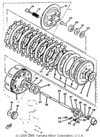
1.3.1 gif

XS1-TX650 clutch

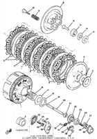
1.3 gif

pre '78 clutch breakdown TX650A on

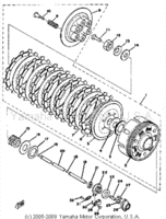
1.4 gif

Late model clutch breakdown

1.5 pdf

- Pressure Plates were also altered, with the addition of a spline, helping load spreading.

PressurePlates.jpg
 

Attachments

  • xs650 clutches 1.3.gifx.gif
    xs650 clutches 1.3.gifx.gif
    18.1 KB · Views: 3,413
  • xs650 clutches 1.4.gifx.gif
    xs650 clutches 1.4.gifx.gif
    26 KB · Views: 4,742
  • xs650 clutches 1.3.1.gifx.gif
    xs650 clutches 1.3.1.gifx.gif
    15.8 KB · Views: 4,352
  • XS650 clutches 1.5 parts.pdf
    14.7 KB · Views: 1,801
  • XS650 clutch plates 1.1.pdf
    4.4 KB · Views: 1,261
Even though some parts diagrams have the last clutch revision (one less friction plate and spring-loaded bottom steel "damper" plate) appearing as early as '78, I don't think they actually came out until '80. I swapped one into my '78 that I got off eBay. Performance-wise, I don't notice much difference but the later style definitely engages smoother when taking off in 1st, thanks no doubt to that spring-loaded bottom "damper" plate. The original mid style clutch always let out with a bit of a "clunk" at the end of the engagement when taking off in 1st.

The clutch is just about the last short coming of my 650 that I've yet to cure. I've tried just about all the recommended fixes and have improved it somewhat, but it's still not perfect. Finding neutral at a stop once hot is still troublesome. Heavy duty springs have cured the slipping but the lever pull is stiff, even with everything lubed up well. I've switched to a Kawasaki perch and lever because it offers a much larger pivot point.
 
5. Modifications:

1. Pushrods…

Models before aug 73 had a single long pushrod (LHS)…those after had 2 shorter.

Cpr.jpg

longandshortpushrods.jpg


Rods and balls dissipate rotational energy imparted from the clutch mechanism. The cups wear and the rods can bend. Don’t lose the balls (long rod-2 balls, short rods-3 balls…5/16”- the last one is inside the worm).

dimpleclutchrods.jpg


Dimpling the ends may help centre the rods, reducing seal and bush wear...however i personally wouldnt recommend it, the tolerances in these clutches are already tight...better by far to get a long rod

After market long rods are, I’m led to believe, stronger. Advantages are a more positive connection and the push rod seal doesn’t wear so fast and leak.

2. Push rod seal…
When replacing these check the bushing behind it, this wears for the same reasons the seals leak. Replacing only the seal when the bush also is worn just wastes your time.

When replacing with original seals buy 2 as you will stuff the first up
Chamfer the outer metal edge.
Coat the edges with some Yamabond equivalent.
They need to go in very straight. Press in with your thumbs.
Normally these seals are Yamaha only and require splitting the cases to replace.

There are kits available using generic seals and adapters.

Lance on 0061-2-95451351 or cell 0061-407-950518. bbillroy@bigpond.net.au

Scc.jpg

closed case
Soc.jpg

open case

or for just the pushrod seal-open case only part nr KU027 webmaster@twins-inn.de

ku027_02_jpg.jpg


3. Replacing bush…
Straight bore for 12mm with 11/32”…follow through with 23/64”…the bush should simply spin out. These are spring bushes. Drive in a new one.

There is a “how to“ on mikexs site… http://www.mikesxs.net/tech_tips.html

4. Cable Guide…
Straightening out the cable guide can remove a little drag.

cablescomparedzv7.jpg


Motion Pro cable on the left, Mikesxs on the right ... take a good look, Mikesxs cables are known to break (he has some good stuff, but a lot of cheap shit too)..Motion Pro cable is definitely stronger

5. Worm…
Over the years Yamaha changed these around a little, mainly altering the pull position, the further out the point of pull the easier the action will be – leverage…the distance of cable pull is fixed so the closer it is fixed to the center of rotation the more rotation you will get and the harder the pull will be.

EarlyWormGear2.jpg

early
midandlatewormgearsio4.jpg

mid late

- or , here, take your choice...hattip pumps :thumbsup:...from the man you love to hate

0425100903-1.jpg


diff worm drives

The final ball is held in the worm gear opening-see above. The stamping holding it in wears out and the ball drops quietly out when removing the cover – take care. Hold it in with lots of fresh grease.

Keep the worm drive clean and well lubricated. The worm housing cracks losing rotational strength, you wont always see it without pressure.

- pic – broken worm ?

More pull for your buck could also be gained by using clutch handles designed to gain length. The closest path between 2 points is a straight line – as you pull the clutch, the cable is tensioned and drawn straight, if you can shape this drawing into an arc rather than a straight line you get more pull per effort.

6. Plates…
You cant get plates for the earlier 6 plate models anymore. Mikesxs and 650Central suggest using the later 7 plate set-up, although theyre thought to increase the incidence of primary dampening spring breakage. Could also swap in the complete later clutch.

.........................Steel............Friction
Pre Aug 73...........1.6mm........6 @ 3.5 mm
Aug 73 – Aug 78...1.4 mm.......7 @ 3.0 mm
Post Aug 78.........1.4 mm.......6 @ 3.0 mm

Many plates are available in standard and performance options.
650 Central carry plates from Ferodo, Pro Bond, Barnett (Kevlar).
When using Ferodo Performance plates the 2 normal plates bracket the perfomance plates...ie 1 normal plate-4 or 5 performance plates-1 normal---hattip: Tim of DO THE TON

I have a billet alu clutch body with 8 friction plates. The steel plates were ground to 1.0 mm, slowly, a bit at a time, so as to avoid warping. This works fine.

There are 2 ways that i am aware of to create an 8 plate clutch
1...reduce the steel plates from 1.4mm to 1.0mm-this creates the space to insert an extra pair of plates-1 steel and 1 fiction into either of the later 2 clutches, or
2...turn the inside of the hub or basket-same thing-on a lathe, taking out just enough to allow insertion of the extra plates, these are of normal thickness, 1.4mm, and not susceptible to deformation like the thinner ones are

The advantage here is that the clutch mechanism is more positive and doesnt slip...the next engine i build will include a billet clutch basket-stronger-turned to allow insertion of normal plates

7. Billet Body…
These are ocassionally available in aircraft quality aluminium and are much stronger than the original.

billetclutch2.jpg

billetclutch1.jpg


billet clutch body

ku039_03_jpg.jpg


from twins-inn germany 292 euro exchanged for your original body and primary gear

8. Springs…
Springs..I dont have originals in front of me so am only going from memory here...XS1 had 38.1mm springs, these were changed to 34.6mm for the XS1B - aug 79, after which 42mm springs were used. Over and above these, are several grades of stronger springs. The stronger the spring the better the contact between plates but the action is harder.

- pics – springs ?

Spring “

Ferodo 1.640
Vesrah 1.835
Barnett 1.50

A better rating would be compressional force required for a given compressed length (ie. 70 lbs/sq in at 0.950”.

9. Screws…
Use #3 bit for original phillips head screws
Allen head screw kits are available. The heads don’t wear so fast, torque setting is easier.
0.8-1.0 kg/m...5-7 ft/lb...9.0-9.5 N.m

clutch_rb11_s.jpg

clutch_rb10_s.jpg

screws

10. Dampening springs…
Found behind the clutch body. Absorb much of the drive train shock and break. Although problematic on all models, those between Aug 73 and Aug 78 were especially bedeviled by this. There are several kits available to repair this- round-section springs, flat-section springs and a mixture of springs and vesconite…use locktite.

clutch5.jpg

clutch3.jpg

vesconite kit

11. Primary Drive Gears…
The clutch is the meat in the sandwich, caught between the clutch hub, direct connected to the gearbox, and the clutch body, direct driven by the crank. The speed the clutch rotates is dependent upon the gearing of the cogs driving it. If you replace the original primary drive gear (72 teeth) riveted to the rear of the clutch body with a smaller diameter high-ratio primary drive gear (68 teeth) and the larger companion crank driver (30T), the clutch rotates faster at any given crankshaft rotation, the gearbox rotates faster as does the rear wheel. Especially when combined with the 5th gear overdrive, clutch slipping can be a problem needing well chosen drive train gearing.

clutchmod.jpg

original
P1000236.jpg

high ratio
primary drive gears

12. Needle Bearing...
Mikesxs sell an improved needle bearing

39-6505.jpg

improved
clutchproblemi.jpg

original
 
13. Centrifugal Aided Clutch…
Centrifugal pressure is additional clamping pressure on the clutch disc that occurs as a function of engine RPM. As engine RPM increases, centrifugal pressure forces the clutch fingers of the Long Style pressure plate outward. As this occurs, the clutch fingers pivot against the cover and apply additional clamp loading to the clutch disc.

P1000480.jpg


centrif clutch mech
http://www.aim-tamachi.com/home.php?cat=29

http://www.aim-tamachi.com/home.php?cat=3

http://www.aim-tamachi.com/home.php?cat=18

http://www.aim-tamachi.com/home.php?cat=36

http://www.thunderproducts.com/Yamaha clutch.htm
…technically for snowmobiles but gives you the idea…check out the UFO, VIP, Glide Washers…

14. Hydraulic Clutch…
Although you need to mount a reservoir the advantage here is that less effort is required to operate the clutch. The action is direct push rather than rotational.

017.jpg

MarkWallace7-1.jpg

c1bd025f.jpg


hydr clutches

15. Pull Clutch…
There are several advantages in doing this. The first is removing the push rods through the motor – closing a potential leak (seal), breaking a chain wont destroy the clutch push-rods and it improves gearing choice ie larger front cog. The mechanism is direct on the RHS.

230004b.jpg

P1000327.jpg


pull clutch

16. Suicide Shift…
Once again there are several options available here. Because you are aiming for a hand shift you need to reposition the clutch actuator. This can be done both for foot, in normal riding position or as forward controls, and for hand as a lever incorporated into the shift.Can be cable or hydraulic.

craig-pics-004.jpg

hand op clutch
feb-003-1024x768.jpg

foot op clutch
P5240251.jpg

forward control-foot

17. Dry Clutch…
This is not an easy challenge. Isolating the clutch from oil is not so simple. There is no aftermarket kit available as for the SR500. For racing I can see the benefit but for normal use the rattling is too harley or ducati like.

Dc3.jpg

dry clutch
clutch_001.jpg

Daryl W.I.P
 
3. XS650 Cables

- ive given cables a section of its own because a high percentage of XS clutch problems are related to the cable or worm drive

Basically 2 types.
1. … multi-stranded wir, wound spring steel-cover-style
2. … Teflon-lined.

Cable parts
http://www.flandersco.com/Feature.html

http://www.legendmcs.com/custom-chrome-harley-parts-handlebars-controls/cable-repair-kits-new.html

Cables have various thicknesses and weaves, ie, a 1x19 cable is 1 twist of 19 strands, a 7x7 is 7 twists of 7 strands twisted together. Often available in stainless steel. Cable and Outer OD and ID must match, dont forget any coating.

Fittings can be cannibalised from old cables. When not, source them. Many modern cables have die-cast zinc fittings, unreuseable, they simply melt. Save old fittings.

When the old cable is not available or youre changing frame dimensions or handlebar height or width, first route for outer sheath length,. This length, between 2 non-moving objects, is fixed, so routing is critical for smooth operation. No binding, No kinks.

Suggestions for proper cable installation:

1. Inspect and make sure you have the correct cable. Inspect for wear and tear.After checking thoroughly, Do you have the correct parts, e.g. correct cable ends, proper size casing ferrules, correct size, shape and thread size of adjusters/elbows, etc.
141_0809_09_zmotorcycle_maintenance.jpg

fraying cable
2848456340057350080S600x600Q85.jpg

2. Ensure all adjusters are in "closed" position.
3. Direct-route cables.
4. Route from control to actuator in the most direct way possible. Keep cables away from hot surfaces. Avoid sharp bends and "kinks" in the housing or inner cable.
5. Route properly. Avoid binding or hanging cables at full lock-to-lock bar movement or during forks and suspension compression.
6. Install lever and actuator fittings. Adjust freeplay to correct specs and check for smooth-positive action.

Like any other motorcycle part, keep cables clean and properly lubricated. Regularly check for proper adjustment and inspect for any wear and tear. Look for torn or worn housings, frayed wires, and signs of bending or kinking at the controls.

Motion-Pro-08-0182-Cable-Luber.jpg

141_0809_10_zmotorcycle_maintenance.jpg


In the good old bad old days, most motorcycle shops made their own cables. Didn’t need much stock, and the process is simple enough.

Repairing cables is difficult - ie, cutting the inner and outer back 25mm or so is simple too, but the inner will be so oily it's almost impossible to clean well enough for solder to stick. Better to make a new inner, using your original outer and fittings. Measure inner length carefully (remember to add missing parts).

If building a totally new cable, you'll want both lengths.

A bulk spool of inner and outer of the desired gauges, and a supply of fittings and nipples are needed. Fittings can be used over and over, nipples not. Go a little larger than stock gauge when making new brake and clutch cables.

Propane torches give better heat and control. Use soldering paste/flux and silver solder (50/50 will do if necessary). Acid core solder is for sheet metal. Heat the nipple without getting the cable too hot – it will lose its strength.

For cleanly cut cable, a GOOD pair of side cutters or nippers is a must. Tin the cable end before cutting as close to tin beginning as possible, or wrap in electrical tape before cutting.

2241108440057350080S600x600Q85.jpg


Tin as close to the nipple as possible - too far up and the cable loses flexibility. Especially important for the throttle cable, grip-end!
2897146900057350080S600x600Q85.jpg

..a bit too much solder up the cable

So, cable's cut, nipple's slid over the tinned end. De-tin the end, splay the strands, pull the cable end back into the nipple until the splayed strands don't quite project out of the recess. If they do, file down after soldering. Remember, if the cable isn't splayed into the recess, it wont hold. The solder simply maintains the splay, preventing nipple pull-through. Flux. Heat. Dip into solder.

2107877500057350080S600x600Q85.jpg

2930727960057350080S600x600Q85.jpg

2765550200057350080S600x600Q85.jpg


Nipple has to be hot enough to melt the solder and flow it into the recess, cable should be hot enough for the solder to stick to the individual strands.

2627892390057350080S600x600Q85.jpg

2897146900057350080S600x600Q85.jpg


LOW FRICTION CONTROL CABLES

Low friction ‘slippery cables’ are high quality PTFE lined, to give low operating force, low maintenance and long life, at competitive prices.
Cables are suppliable with nipples to suit most applications. Not normally custom built, can be made to specification if demand requires. Standard outer cable length (conduit) is 1.5m, inner - 200mm longer. 7x7 galvanised high tensile steel inners are recommended for throttle and choke, 1x19 galvanised high tensile steel for clutch and brake. When making, dont worry about melting teflon.

CONTROL CABLE DIMENSIONS
STANDARD 1.5 m SHORT 1.0 m LONG 2.0 m
TYPE...................OUTER CONDUIT.....END CAP...........WIRE
AT............................3/16" 5mm.....7/32"-5.4mm .....0.058" 1.47mm
.........................................................................0.062 1.60mm
AC............................7/32"-5.4mm....1/4-6.4mm......0.070 1.77mm
.........................................................................0.080 2.00mm
.........................................................................0.093 2.50mm
.........................................................................0.120 3.00mm
...............................1/4"-6.4mm....5/16-8.0 mm......0.120 3.00mm
AB...........................1/4-6.4mm.....5/16-8.0 mm......0.126 3.20mm

AT.... Throttle, choke and timing etc. AC....Clutch and light brake. AB...Brake and heavy clutch

Lubing Cable

Clutch getting harder to operate? Well, it’s probably not arthritis and wont cost your soul to get moving smoothly again. Mostly, simply lubricating the cable does it. Extreme cases of cable wear or fraying, require replacement.
Sticky, binding cables are the pits. There is no control whatsoever. They “go” at the least desireable Murphy Moments taking the air out of your hair. Generally it’s a long push.

Things You'll Need:
• Assortment of screwdrivers
• Small set of box-end wrenches
• 1 can degreaser
• 1 can good-quality lubrication spray
• 1 adjustable pliers/needle-nose pliers
• 1 cable lubrication tool
Preventative maintenance goes a long way toward extended smooth operation.
Do NOT use oil based products. They attract and absorb dirt and become sticky. Use a very thin lubricant (Bike Aid Film Lubricant, Dri-Slide, PJ-1 Cable Lube etc)

Basically 2 types.
… multi-stranded wire surrounded by a wound spring steel-cover-style
… high-tech Teflon-lined.

Teflon-lined cable needs no lubrication, oiling may be detrimental. Check instructions for recommendations.

1. Disconnect the cables from levers/controls.
2. Disconnect the operating end using needle-nose pliers.
3. Connect cable lubricator to the lever end, make sure it seals
4. Spray cleaner/degreaser liberally flushing out dirt and grime.
5. Apply lubrication in the same manner.
6. Rearrange the cable using the same route or path as original.
7. Reconnect the cable ends, replacing any mounting brackets removed earlier.
8. Squeeze the clutch lever several time and ensure the ferrule is properly seated
9. Adjust cable pull until there is a 1/16" to 1/8" gap.
10. Start the engine and check for proper operation and enjoy your ride.
Inspect the nipple and adjacent cable for signs of damage. Before reinstalling, dab a little grease on the nipple to prevent from binding.
To ensure positive karmic balance, take 2 doses per year.

Motion-Pro-08-0182-Cable-Luber.jpg
 
XS650 CLUTCH CABLE ADJUSTMENT

Be aware that there are 2 adjustment settings for XS650s, cold and hot. The push rods that transfer the worm gear action to the clutch pressure plate are made from steel. These transverse the motor and seat in aluminium. Aluminium thermally expands faster and further than steel giving XSive end play as the motor warms up.

Cold Adjustment...
1. Remove left casing, release cable
2. Clean and lube cable
3. Clean and lube worm gear
4. Repack the ball bearing with grease
5. Remove and clean the push rod, reinstall
6. Reinstall cable
7. Back the worm gear screw out 1/8th turn...pump the lever in and out just enough to take up the free play (don't pull all the way in). This "stacks" the push rods and balls together, taking up any slack and squeezing excess oil out from between them – gives a more accurate "feel" for the rod free play and adjustment.
8. Adjust the lever play to almost nil
9. After 20 minutes or so riding, readjust lever free-play

Your clutch should now operate smoothly, like new. If still hard, the cable may be worn or frayed and should be replaced.

After any service, test ride your motorcycle in a controlled situation before riding in traffic.

You would not believe how many people think they have a clutch problem just because the lever is hard to pull.
 
2. Assembly

First thing to remember here is that, in their wisdom, Yamaha left a Thrust Washer off the diagrams. Between hub and boss they show a washer (25-50-2) and a thrust bearing – missing is the washer (31-51-0.5) between needle bearing and hub..(e)..

clutchh.jpg


Next point to remember is 2-2-2…each step requires 2 washers..see above diagram

Install:
2 washers/shaft-to-hub-bush (hub) thrust bearing/2 washers (boss) 2 washers/nut

*Crankcase
*Bush
*Washer..25.2-36-1.0
*Washer…25-50-2
*Hub
*Washer…35-51-0.5 **this is usually missing from diagrams, therefore gets left out**
*Thrust Bearing
*Washer…25-50-2
*Boss
*Washer…plain
*Washer…Spring Bellville/lock washer
*Nut
*Push Rod End

This sequence ignores plate packing and Mikesxs recommendation that you pack thrust bearing direct against hub, then covered by the 2 washers.

Also be aware that when the internal 2 piece push rod was introduced many parts books and manuals showed, in pictures, installation with the turned down end pointed towards the clutch hub, instead, this reduced end locates into the worm gear pushing against the ball bearing crimped into it...you will know its installed wrong when you either cant close the case or have no pressure at the clutch handle

So, before starting check the 2 shift mechanism springs

t_shifterspring_985.jpg


xs650rightur2.jpg


Ensure:
-the spacer is ok
-you have the 2 washers
-there are no rubbing marks
t_clutch_rubbing_mod1.jpg


-the primary drive dampening springs are intact
clutchmod.jpg


-the hub basket dogs are not worn, cracked, bent, broken..bent/broken, replace-rilled, if not too bad lightly file-reduces friction plate catching, if bad, replace

clutch_rb7_s.jpg


clutch_rb4_s.jpg


clutch_rb3_s.jpg


…install…
-thin washer
-bearing…mikesxs has a good replacement
39-6505.jpg


-thick washer
-boss, check that splines are not worn
clutch_rb8_s.jpg

-washer
-spring/lock washer
-nut...18mm...55-59 ft/lb...80 N.m...8.1 kg/m
p6140697.jpg

…install…
-make sure the ball bearing is in the shaft…oil
-push rod(s - bearing)
…install clutch pack…
-pressure plate…if yours has splines make sure they register
PressurePlates.jpg

-springs…all same size and within specs
-screws…tighten with impact driver - 5-7 ft/lb...9.0-9.5 N.m...0.8-1.0 kg/m...use #3 bit so you dont damage the phillips head

CLUTCH PACKS

The different packs, 6-7-6 plates, are interchangeable as a unit. As the early, thicker plates (3.5mm) are not available anymore, Mikesxs suggest removing the rubber rings and installing an extra steel and friction plate pair in the early clutch packs.
The 7 plate pack is known to increase risk of primary gear dampening spring failure.

My personal suggestion is to change in a later model 6 plate pack - straight swap.

When installing
- soak new friction plates in oil-overnight if possible...Note that your bike needs 20W-40, which is available at truck stops and auto stores...eg Shell Rotella, Pennzoil without the additives found in modern automobile motor oils. Wrong oil = clutch problems...big time!!!
- check steel plates for warping-lay on plate glass, if you can rock it or slide a 0.008"(0.2mm) feeler guage under, replace
- buff the sharp edges smooth...as these are stamped-out, the top edges are rounded by the die, the bottom edges are left sharp...buff these smooth with a wire wheel
- scuff the surfaces lightly with emery paper to remove glazing - wash
- check friction plates for wear...new-3.0mm...min-2.7mmm (earlier, 3.5mm new/3.1mm min)
- lightly bevel the edges of the friction plate tabs with a file...this helps prevent them catching on the basket fingers

NOTE...when installing the later sprung 6 plate pack, be aware that there are 2 different steel plates...the plate that belongs to the anti loading pack that goes into the boss first is thicker than the others, 1.6mm as opposed to 1.4mm - dont mix them up

Alignment

- if not aligned properly the cluth will be noisy and not work properly
pressureplategroovesremovedmod1.jpg

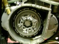
...this hole must align with the mark on the boss
ClutchIndexHoles.jpg

...like this
ClutchIndexSet.jpg

...when there is no mark or hole then align as below...only 1 screw boss lines up with a tooth centre-this is where the pressure plate must align...mark the tooth
ClutchInnerHubArrow.jpg
 
Worm gear ball crimps .....

jf4wS0Y.jpg


And the larger pivot on my Kawasaki clutch lever/perch assembly (bottom) compared to the original .....

phDcC2H.jpg
 
Last edited:
My xs in the uk has been slightly altered to take 2 extra plates,as usuall I can't remember the exact dimensions but i think you take .5mm off the back of the basket and either 1 or 1.5 mm off the pressure plate this tightens it all up,but I think you can only do this to the euro models,not sure why,and I might be wrong
 
4. Problems

I will divide these into 2 types
- associated with repair (just repaired your bike and the clutch wont work)
- time related

a. associated with repair

- so, what did you do and how could that mess with the clutch?
- had the LHS case off
- lost the ball bearing from the worm drive​
- worm not adjusted​
- cable not adjusted​
- cleaned and lubed worm gear - hat tip-jay​
- reinstalled worm gear in wrong spline​
- had the push rod out(and hopefully cleaned and polished it)​
- installed the rod with small end in​
- installed offset kit
- need longer push rod​
- had the RHS case off - clutch repair
- assembly problem...remember 2-2-2​
- needle thrust bearing improperly seated​
- had the RHS case off - kickstart repair
- read Clymer-covers this well​

b. time related

- general wear and tear, maintenance issues

- bike has been sitting, no clutch-frozen
- check cable, clean and lubricate or replace​
- on centrestand, move wheel by hand, or​
- put in gear and rock-use gentle loving aggression, or​
- roll-start, or​
- start,roll, put into 2nd gear​
- clutch slips
- not adjusted correctly​
- cable too short​
- friction discs worn, warped, oil saturated​
- wrong oil...20W/40 with few modifiers​
- clutch springs damaged or weak​
- clutch springs not tightened properly​
- ball bearing missing​
- alignment problem​
- clutch drags or stalls in first gear​
- not adjusted correctly​
- oil dirty or too heavy for climate​
- friction plates gummed​
- steel plates warped​
- spring tensions not even​
- push rod bent​
- grooved hub/basket fingers​
- worm housing broken​
- clutch noisy
- not aligned properly​
- primary gear damping springs broken​
- hub bush worn​
- boss or mainshaft splines worn​
- plate tab/hub clearance too big-clunk​
- pressure plate hitting sidecover​
- brake pedal indent from being dropped​
- gears wont shift
- clutch dragging​
- shifting difficult-gearbox grinds when shifting
- not adjusted properly​
- oil too heavy for temp​
- shudder on take-off
- alignment​
- spline grooving​
- cable needs lubing​
- thrust washer missing​
- lever moves, nothing else
- broken cable​
- worm gear cable holder broken​
 
Last edited:
I'll add another to that which I'm almost ashamed to admit,I had the left cover off once put everything back together to find I had an exess of cable which I adjusted out on the tensioners without thinking to much about it,only to find my clutch wasn't working very well when I looked into it when I put the cover back on in my haste I located the worm in the wrong spline so it pulled a bit but not nearly enough.
 
Another one: A friend wanted to remove the YAHMAHA lettering out of the right side cover, so he had another friend (who wasn't very good at welding aluminum) try to fill the letters. Well he must have burned through a couple of times because he ended up laying a couple of beads on the inside of the cover behind where the lettering would be. The cover went on fine, but when you would pull in the clutch lever, the lever felt fine, but it wouldn't disengage properly because the pressure plate hitting the weld. They pulled the side cover off, ground down the weld, put it back on, and everything was fine.
 
- what is the story with the centrifugal assist - was this specially made or a bolt on
- did the clutch pack bolt straight in or were there installation modifications required

- what is the operational difference to the XS
 
The centrifugal assist was made for the banshee,I had to modify the holes to the spacing of the xs bolt centers. approx. .030 out.
that is a stock 650 clutch pack.I also had to make spacers for the springs and to get the lock-up head in the right position.
I also had to redo the side cover.
 
I don't really understand how those centrifugal clutches work, anyone have a diagram or good way to explain how it works?
 
...its not a centrifugal clutch...its an assist...the counterweights are mounted assymetrically - the mounting point acts as a fulcrum, as the clutch spins faster the weights are thrown out - there is more weight outside the mount than inside - and the weight foot puts pressure on the pressure plate which transfers this to the clutch plates - ie. it removes the potential for slipping - the further out the weights are flung the more the pressure on the clutch
 
Back
Top