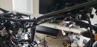
Comparing the harnesses, it looks like the me in the past was smart enough to label a good bit of connectors, and a lot of them match the colors on the new harness... Perhaps I just forget where that damn thing goes on this bike. Going to have to buy some butt connectors and shrink tube to splice some connectors to this harness so it works for me.
-
Enjoy XS650.com? Consider making a donation to help support the site.
XS650.com receives a small share of sales from some links on this page, but direct donations have a much greater impact on keeping this site going.
You are using an out of date browser. It may not display this or other websites correctly.
You should upgrade or use an alternative browser.
You should upgrade or use an alternative browser.
Yam_Tech314's official build thread
- Thread starter G_YamTech_314
- Start date
I found the location for the light checker... I'm gonna try exercising more of my brain, and we'll see where that gets me...
The light checker is usually located behind the battery box and difficult to see or access unless you remove the inner plastic fender .....

You should have the simple 3 wire unit. All it monitors is the brake light. It can be eliminated by simply unplugging it and removing it. No jumper wires are needed.
You should have the simple 3 wire unit. All it monitors is the brake light. It can be eliminated by simply unplugging it and removing it. No jumper wires are needed.
Thanks a ton 5twins! I appreciate it... This harness actually appears to be a pretty good fit for the bike. Once I wrapped my head around it things kinda came back into my mind and jogged my memory. The hardest part I'm finding is the routing of the harness... Im also having a tough time with parts that get plugged into the motor. With it being off the bike, there's a lot of connectors that just get left hanging until the motor is in... Installing the motor may be the best option for testing after all, either that, or I rip apart all the components I just put on and plugged into the main harness... Either way, I'll figure it out with enough time.
Oh. I definitely didn't have a self cancelling unit. But good to know that I can (maybe) put one on the bike... I didn't know they made self cancelling signals in the 70's.
As far as the harness goes, I have it mostly routed in a way that I believe will work. A few things to tweak here and there still, but it's almost one step closer to being a motorcycle!
As far as the harness goes, I have it mostly routed in a way that I believe will work. A few things to tweak here and there still, but it's almost one step closer to being a motorcycle!


One more oversight I found while tinkering today is the rear brake light switch. I'm going to assume they differ from drum to disc in the way they operate and are mounted. Simply because one is hydraulic and lacks a pushrod. Also, if my memory serves me well, the drum style switch is a button type that is activated by the drum itself.
If I am to wire a rear brake light switch for div type do I need to do more splicing and dicing, or will it be more or less plug and play? Will it require creativity to mount to my swingarm/'76 frame?? Just some stuff I thought about.
If I am to wire a rear brake light switch for div type do I need to do more splicing and dicing, or will it be more or less plug and play? Will it require creativity to mount to my swingarm/'76 frame?? Just some stuff I thought about.
My old RD250B had a front disk brake and the brake light was activated by a pressure switch set in the hydraulic line. If you had to you could probably fit a pressure switch in the rear hydraulic line. Perhaps someone on the forum may have done this in the past?

I just noticed that break and brake are anagrams. Now that's got to be worth a thought or two .
.
I just noticed that break and brake are anagrams. Now that's got to be worth a thought or two
.
Last edited:
Could anyone help me identify the year range that this switch would have been used? I know it's not a 76 because the 76 wiring had single male connectors on each switch. There was no multi pin connector. I'm willing to cut the connector and install single pins if that will work, just trying to get a better idea of what year it's from.
Attachments


You got it! I'll post pictures of the engine stop switch too. Not sure either of them are '76
Engine stop switch is just three wires, brown, blue/white, and red/white.
Left side switches (signal, horn, lights) has blue/white, yellow/red, brown/white, pink, yellow/black, blue/green on the six pin connector. Aside from the connector there's dark green, yellow, light green, black, and brown(?) The brown is almost a black.
Attachments


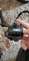

Since your right control doesn't have the headlight on-off switch, that would make it '79 or newer. I'm going to guess the left control is a match and the same. They probably came along with the front end swap. Personally, I'd be looking for a right side replacement, yours looks pretty beat. And besides, I think you want an older version with the headlight on-off switch. Last year for it was '78.
I agree. I've decided to modify the new harness by doing nothing to it.
Meaning: I only wanna add to it. I spliced in the old wiring that connects the horn to the harness by using plugs on either side. I spliced a male plug to a female plug, and bridged the horn to the harness and protected the joints with shrink tube, then nearly tucked the wiring between where the coils will hide it. I plan to do this with everything else I will have to modify. My hopes with this method is to avoid a headache for the future. If anything ever needs changed it can all be unplugged from the harness rather than cut out.
As far as switches go, it will also be nice to have the same color wiring, and potentially the proper plugs for the harness I installed. The less I need to modify the better. At least until it's running and riding.
Attachments

More electrical findings... It seems that I may have coils from a 1974... Orange and brown wires on both. Following diagrams from the '74 I connect both coils brown to red/yellow while both orange dangle there until my motor is installed and can be hooked to the condensers. This is another reason I'm making jumpers to connect everything. If anything happens to be wrong it can just be unplugged and made right. As long as I don't fry the whole harness. But that's unlikely as long as I wire the battery right... Right..? Right. We hope so anyways.
If you are concerned about burning the harness while setting things up then replace the main fuse with something lower like 15A or even 10A, but keep the headlight and horn off - big current users.
I need to figure out where I wanna put the main fuse. To my knowledge it goes between starter solenoid, and the battery somewhere in the circuit. Way back when I tore the old harness down, they bridged a broken glass fuse with some copper wire and rabbit that way. I am tossing around the idea of a fuse box but that would be later down the road. For now I'll likely just do what I have been doing and extend the harness with connectors I make, and route some of them through a 10 amp for testing and a 15 amp for daily use.
The "brown wire " is not brown but chocolate and is the hot wire for the turn signal on one side. Don't remember which side but it is labeled as chocolate on the factory diagramsgreen, black, and brown(?) The brown is almost a black.
One thing I would suggest after looking at the pictures is to invest in some OEM style metal wire ties. The plastic ones don't hold up so well at least down here where it get hot. Especially above the engine.
Those original black plastic coated Aluminum ties are £2 each in the UK and about £1.30 without the plastic, but you would probably only need four. I have seen stainless steel zip tips mentioned on other forums, are they cheaper and better??
Edit: Stainless steel and about 1/10th the price.
Edit: Stainless steel and about 1/10th the price.
Similar threads
- Replies
- 214
- Views
- 26K
- Replies
- 98
- Views
- 8K