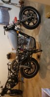
Yam_Tech314's official build thread

Oil scrapper rings as far as I know have no top or bottom. Top 2 rings for compression do. Oil rings just need to be installed correctly.
What he said.
Oil rings (called rail rings in a 3 piece ring) can go either way. Top two depend. some will go either way. Some will have a marking that goes up. And some will just have an edge that looks different to the other edges. It goes up.

PXL_20210609_233102638.jpg
 
I felt for different feeling edges, couldn't tell a difference. Hopefully it's right :laughing:

We will find out soon enough.

Saying that the valve clearances are too tight... Should I change that? Or is it good enough to test run the bike? I really don't wanna mess with it right now... Lol.

I'm getting excited though. We got it looking like a bike now!!! :bike:
 

Attachments

  • Snapchat-558731582.jpg
    Snapchat-558731582.jpg
    137.7 KB · Views: 59
Setting the valves on these is no big deal and it gets easier the more you do it. And since it's something that will always need to be done, you might as well practice up and get good at it, lol.
 
Wasn't the head rebuilt? Think about as the valves seat or break in, what effect would that have on the stem clearance?
Can expect it to get tighter soon right..
 
Speaking of oil... The capacity doesn't differ from model to model does it? I still just rest the dipstick in the hole NOT screwed in and read the level that way yes? Should be close to 2.5 quarts?
 
Just an fyi...
Valve lash clearances can increase or decrease as the engine wears. Depends on what's wearing down.
Parts that cause an increase in clearances are the tip of the valve stems, the adjusters, the rockers (and shafts) and the cam lobes. You could also include the cam bearings here but that would become obvious long before you were worried about clearances.
Parts that cause a decrease in clearances are the valve face and the valve seat.
Provided the valves were properly lapped in, you shouldn't see any significant change in lash as the engine wears in. This all refers to a rebuilt top end obviously. Valve lash on a new engine can change significantly, depending on manufacturing quality.
 
The valves had a really nice cut job done to them same with the seats. I trust the machinist with just about anything after seeing how some of my cousins cars have ran. Looking at the valves when I got them back I noticed he ground a fresh face on the back of the stem as well so Amy wear that would have been there no longer is. They'll wear in a fresh new divot on the back of the stem. My guess is that he wanted to see them all be perfectly flat? Either way, he seems to have done a good job this far.
 
Woke up this morning to oil on the catch pan I placed under the motor overnight.

My guess is that because I squirted oil on the cam and rockers that it dripped down and out through the clutch pushrod seal. I never put the long one piece push rod in, and didn't think anything of it, but I kicked the motor over a bunch to try and prime it lastnight, and also squirted oil into the top end... Think that's what did it? I'll take pix later.


In other news, I've been sick all week so I've been staying home from work, and that's why I've made so much progress. I'm not the type to lay around. But I didn't wanna give anyone at work what I got, so home was where I stayed.

I tried to go back this morning, and they sent me home until I can provide a Dr.s note... But they waited to tell me that til I drove 30 minutes to be there.

On the bright side (no pun intended) I witnessed the solar eclipse this morning.

Fate made it so. If I hadn't been sent home I'd be welding up a trailer as the eclipse ran it's course. I pulled over to enjoy staring at the sun for a few seconds.
 

Attachments

  • 20210610_062307.jpg
    20210610_062307.jpg
    49 KB · Views: 68
Yes, with the long one piece rod, one ball first, and only one. Fill the seal lip with grease before inserting the rod .....

3iddQQH.jpg


And after it's in, coat the exposed portion with some grease to ward off corrosion .....

ySjlsqO.jpg
 
Common sense tells me this piece goes in with the raised collar in towards the housing

However, the marring on the collar side suggests tampering from the PO. How does it go in, and should I deburr it? Also, what tool do I use to properly tighten it??? Should I install and torque the retaining star nut before putting the arms and springs and e clips in??? Wow, I thought this was simple. Lol my guess is that flat side goes in
 

Attachments

  • 16239705118305528407340323275020.jpg
    16239705118305528407340323275020.jpg
    47.9 KB · Views: 55
  • 16239706078628444991565336413450.jpg
    16239706078628444991565336413450.jpg
    77.5 KB · Views: 49
Another (maybe more important) question is about the screws that hold the points housing in place. It looks like there should be spacers or washers behind them to snugly secure the points in place. I'm sure this isn't supposed to wobble around freely inside the motor... Does it need to be turned clockwise/counterclockwise to advance or retard the timing? Where should I set it??? My PDFs have no manual on this part of the motor... Go figure.
 

Attachments

  • 16239711623496640977437286520276.jpg
    16239711623496640977437286520276.jpg
    129.3 KB · Views: 54
That notched ring gets installed with the lip facing out. You just use a hammer and punch on it to tighten it up. You can see by the buggered up slots that someone has done so already, maybe over-done it a bit, lol. I anti-seize the end of the cam where the advance unit slips on and the threads for the notched ring. You want to do the end of the cam because both it and the advance unit are just plain steel and can rust together. Having it on the threads just makes the ring go on smoother and better.

EOzB3RW.jpg


Yes, those screws that hold the points plate on should have washers. Your screws don't look like the right ones. They look like the screws that hold the chrome cover on. According to the parts listing, the screws are an M6 x 14, but originals are sort of special. They can use either a Phillips or a straight blade screwdriver .....

yNdLlJU.jpg


The replacements Yamaha sells now just look like plain Phillips screws (#28) .....

https://www.partzilla.com/catalog/y.../cylinder-head-cylinder-head-cover-xs650d-e-e

Some guys replace them with Allens.
 
Last edited:
Rotating the points plate clockwise advances the timing, counterclockwise retards it. As the pic in the previous post shows, you usually scribe a line between the plate and the housing so you can put it back on and have the timing be reasonably close. But, if you've done a rebuild and replaced a worn, stretched timing chain, the marks you made won't be right anymore, lol. So, you could probably set yours in the middle of the slot to start. Once you get it running, you can fine tune the timing.
 
I couldn't find any M6x14's so I went with M6x12's and figured I'd just go easy on them when tightening them down. The only other hardware I managed to find was M6x20... It's a big jump, and I wish they just carried what I need but that's the story of my life.

As long as I don't tighten them down too hard I think they'll hold just fine and not damage threads. That being said, I also couldn't find washers that looked like they'd fit the role so I bought two M5 fender washers that were only a bit wider than the head of the screw and used a countersink bit to real the center out until I could slide the M6 screws in.

I'm left with one final challenge to wrap this ignition system up... Setting the timing. I kind of eyed up the center of the notch with the hole in the motor where the screw belongs. Is that gonna be good 'nuff for a first start when the time comes?

This is what the final product looks like!
 

Attachments

  • 16240556782857507486799922242230.jpg
    16240556782857507486799922242230.jpg
    137.1 KB · Views: 60
  • 16240557216012956108325947918921.jpg
    16240557216012956108325947918921.jpg
    162.6 KB · Views: 65
  • 16240558654681783668801098310633.jpg
    16240558654681783668801098310633.jpg
    60.4 KB · Views: 60
  • 16240559252712022167082187946888.jpg
    16240559252712022167082187946888.jpg
    130.1 KB · Views: 63
The only issue I see is I think you assembled your advance unit wrong. See that slash mark on the little disc? It's supposed to point to a slash mark etched in the advance backing plate. Yours doesn't, it's 180° off. That means the timing will be 180° off too, lol. It should look like this .....

oOmaPmF.jpg


The little locating pin for the little disc in the advance rod can be stuck in either side of the rod. To get the timing right, you have to match it to the locating pin for the points cam on the other side. They both need to point in the same direction .....

LhHXTz4.jpg


Your locating pins are 180° off from one another now, pointing in opposite directions, and that's going to throw the timing off 180°.

Once you have that corrected, will it start where you have the timing set? Well, you'll just have to try it and see. If it won't start, move the plate a little one way or the other and try again. Or, static set the timing like in Jim's video.
 
Back
Top