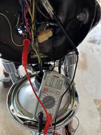
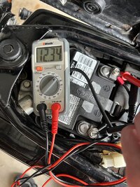
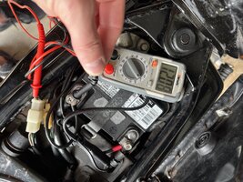
Well, not quite as correctly as most of us like to see. As mentioned, we like to see the low 14's, ideally like 14.2 or 14.3. Get below 14 and the battery may never be brought to a full charge.
Several years back, when I first started getting into the electrical more, and finally checked the charging output on my '78, I found it a bit low, only in the high 13's. Now, I never had battery issues, never had a dead battery, from running it like this but apparently I wasn't giving the battery quite as much charging voltage as it would have liked. The simple regulator adjustment cured it, and then an upgrade to the VR115 auto regulator really fixed it .....
View attachment 239244