WELSH FLAT TRACK REVIVAL

Not sure I understand it correct .. ( the language )
Please disregard if off ..
Are you having a swing 17 mm hole but the new hub have hole 20 mm
Not checked the drawing but is it not Husqvarna spec I am thinking a pipe inside for distance. Between the bearings
I would look into the possibility replacing the 20 mm bearing for one with a 17 mm hole perhaps need the pipe also.

Too bad no one makes the conversion bearing.

same outer diameter and the same length transversely.
Bearings have many manufacturers . A radial difference of 1.5 mm can perhaps be found
If some cooperation measurements can be found from Husqvarna 17 mm and Cognito or Yamaha
If I should guess the tight fit is on the wheel hub and the axle fit is a bit more loose
( safety the wheel can rotate on the axle a bit )

If this is not totally wrong and you have info on the bearing width ( measurement transversely ) I have a SKF catalogue I can take a quick look in
 
There may be an easier way to get the 17mm axle to work. A 6403 bearing has a 17mm I.D. and 62mm O.D. so could replace the original left side 6305. That would just leave adapting the right side. The 6304 used on the right was also used on the left on XS500 rear mags. They use a 17mm axle and adapt the bearing using a tophat insert like the 650 left bearing does. If you could find one of those, I think you'd be all set. Part #10 in this drawing .....

https://www.partzilla.com/catalog/yamaha/motorcycle/1977/xs500d/rear-wheel
 
Not sure I understand it correct .. ( the language )
Please disregard if off ..
Are you having a swing 17 mm hole but the new hub have hole 20 mm
Not checked the drawing but is it not Husqvarna spec I am thinking a pipe inside for distance. Between the bearings
I would look into the possibility replacing the 20 mm bearing for one with a 17 mm hole perhaps need the pipe also.

Too bad no one makes the conversion bearing.

same outer diameter and the same length transversely.
Bearings have many manufacturers . A radial difference of 1.5 mm can perhaps be found
If some cooperation measurements can be found from Husqvarna 17 mm and Cognito or Yamaha
If I should guess the tight fit is on the wheel hub and the axle fit is a bit more loose
( safety the wheel can rotate on the axle a bit )

If this is not totally wrong and you have info on the bearing width ( measurement transversely ) I have a SKF catalogue I can take a quick look in
Thanks Jan
I will look into this more tomorrow.
Today I just pulled it all out to get a general feel for the job in hand (pun intended).
I need to think about options as I do not have a lathe or milling machine.
Half mile has done similar work so I will try and follow his lead.
Cheers.
Ads.
 
There may be an easier way to get the 17mm axle to work. A 6403 bearing has a 17mm I.D. and 62mm O.D. so could replace the original left side 6305. That would just leave adapting the right side. The 6304 used on the right was also used on the left on XS500 rear mags. They use a 17mm axle and adapt the bearing using a tophat insert like the 650 left bearing does. If you could find one of those, I think you'd be all set. Part #10 in this drawing .....

https://www.partzilla.com/catalog/yamaha/motorcycle/1977/xs500d/rear-wheel
Hello 5T.
That sounds like a soloution that may suit my needs.
As I don’t have machining equipment, adaption as you describe may work for me.
Then some easily made spacers could take up the slack.
I will check out your links and post back.
Cheers
Ads.
 
6403 and 6304? Are the same? These would be a piece of cake. would just have to make a new inside pipe spacer.:thumbsup: When I made the reducer sleeve-spacer for the 20mm bng I made the sleeve long enough to go into the inner pipe spacer also.
 
6403 and 6304? Are the same? These would be a piece of cake. would just have to make a new inside pipe spacer.:thumbsup: When I made the reducer sleeve-spacer for the 20mm bng I made the sleeve long enough to go into the inner pipe spacer also.
Thanks Halfmile, it sounds encouraging.
I will investigate and post back ASAP.
Thanks to you and 5T for the time to look at options to help me out.
Ads.
 
Hello 5T and Halfmile.
Just measured the supplied bearings from COGNITO MOTO - OSD: 52mm / ISD: 20mm
I cant seem to find any bearings with OSD: 52mm / ISD: 17mm; still looking but not a readily available size.
The 'Top-Hat' spacer / sleeve bush 5T mentioned may be the only option (or get a machine shop to make them?).
Or may have to revert to opening up the swing-arm slots and adjuster blocks.
 
If I go with the Honda CB750 spindle; what model / year should I look forward to?
 
The 'Top-Hat' spacer / sleeve bush 5T mentioned may be the only option (or get a machine shop to make them?).
Or may have to revert to opening up the swing-arm slots and adjuster blocks.
Adam, big danger of teaching Granny to suck eggs, like you I struggle along without lathe, stand drill, machine press or so forth in the garage. When I need a machined part like your spacers or top hat I will do a technical drawing, mark up the dimensions and take to an engineer or machinist. Have used an agricultural engineer in the village we live in but now usually head to a general engineers in Galashiels - most of the employees have bikes or used to have and they seem willing to undertake these small jobs for cash remuneration.
 
Adam, big danger of teaching Granny to suck eggs, like you I struggle along without lathe, stand drill, machine press or so forth in the garage. When I need a machined part like your spacers or top hat I will do a technical drawing, mark up the dimensions and take to an engineer or machinist. Have used an agricultural engineer in the village we live in but now usually head to a general engineers in Galashiels - most of the employees have bikes or used to have and they seem willing to undertake these small jobs for cash remuneration.
Cheers Raymond.
Its times like this I really miss my Dad. He built his own metal lathe (And a wood turning lathe) using old machine parts from work and motors from washing machines. There was nothing he couldn't turn his hand to. Sadly after he died most of his tools and kit were stolen from his workshop. Below is a scale model galleon he built from the ships plans; all the blocks and cannons were turned on his lathe.

IMG_1397.JPEG


IMG_1399.JPEG
 
Nice one Jan and thanks for the tabs.
 
NEW REAR WHEEL JOY:laugh2:

After a life time of false starts I now have my new rear wheel.
This was a brand new 18" rim built onto the Cognito Moto disc conversion hub.
Spoke are stainless steel double butted and polished.

IMG_1531.jpeg


IMG_1532.jpeg


The wheel needs a degrease and clean which will be done after installation and alignment.
Im really pleased with the result and the quality of the build by Dave of Bespoked Wheels: 07969153555 Email: tugboatdave@hotmail.co.uk

The reason for the wheel change is documented in the build thread above; short answer is I can now run a 'normal' 33t sprocket instead of the 40t wheelie prone one the bike came with.

IMG_1533 2.jpeg
IMG_1534.jpeg


This is the first offer up to the swing arm to check alignment and spacing; also the fit location of the disc in the calliper.
New sprocket and new disc temporarily installed with three bolts each to check clearance etc. Old chain being used.

IMG_1535.jpeg
IMG_1536.jpeg


Initially all appeared good, but I could hear some occasional clicks and rubbing on the disc side.
The disc calliper pin on the swing arm was fouling the disc and disc bolt head.
This hub is wider than the old one by 8mm hence the problem.

IMG_1537.jpeg
IMG_1538.jpeg


So I marked the cut off required @ 5mm and set about it with the grinder. I have left enough pin so I can run the old wheel for light off road excursions.

IMG_1539.jpeg
IMG_1543.jpeg

I now need to get the axle spacers machined, and checked the off-set on the rim which can be altered about 4-5mm either way.

IMG_1546.jpeg
IMG_1544.jpeg


above image shows clearance gained and wheel now spins freely.

Once again work gets in the way so I will have to follow up later in the week.

Best regards,
Ads. :devil:
 
Well done getting to know your bike through all that work. Hopefully soon you can collect your reward, some proper riding which you're gonna enjoy.
 
THE DE-WIRE BEGINS: Phase One

Some delays with this build due to work commitments (Wish I could retire; not enough money or pension! :shrug:); and a bout of COVID.
I have never before attempted to rewire a complete bike so feel free to make observations or recommendations as I go.

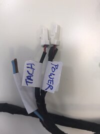
I have decided to strip most of the wire harness off the machine. Taking lots of pictures and labeling various plugs & connectors for reference.
JUST SOME OF THE IMAGES:
D BLOCK 6.JPEG
ID BLOCK 1.JPEG
ID BLOCK 2.JPEG
HEADLIGHT.JPEG
STARTER SOLENOID.JPEG


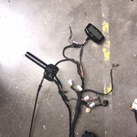
So I ended up with the harness off the bike ready to harvest anything I might need later; fittings, connectors Etc....

LOOM 1.JPEG
LOOM 2.JPEG
LOOM 3.JPEG


Harvesting time on my office desk:

LOOM HARVEST 1.JPEG
LOOM LABELLING 1.JPEG
LOOM LABELLING 2.JPEG


Throttle assembly / Reg-Rec and Digital Dash Etc all came away. Throttle and dash will be replaced entirely.

Bike now looks quite bare with this lot removed:

STRIPPED BIKE.JPEG
UNDERSEAT1.JPEG


The right image above shows at the bottom what I think are lighting relays?
The bike will get a full Moto-Gadget system and I dont think these show anywhere on their installation diagrams.
Am I right in thinking the solid state circuitry on the M-Unit does not need these as it has built in protection?
I'm aware the M-Unit replaces all but the main fuse in the system.

The ignition part of the system will largely remain unchanged; with the exception of a few cable repairs or adjustments.
The bike ran well before I started this part of its evolution; so see no reason to change anything.

I originally though the custom loom was a bit of a 'Franken-Loom' as it appeared to be a hack job when on the bike.
But on close inspection it is actually very well done, once all the dirt and old tape was removed.
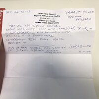
I also found an old envelope tucked under the battery holder showing work carried out by a previous shop in June 2013.

IMG_1677.jpeg

I may try to contact them and get some history on the machine.

Another issue is the under seat tray holding this lot has a break on one mounting Lug.
My mechanic mate offered to weld it back; but I dont want to damage the frame too much.
Would Brass brazing be acceptable; I did some of this back in my school tech lessons?
Or could I get away with J-B Weld?

IMG_1678.jpeg


Just waiting for my new throttle assembly so I can start the handlebar controls layout, then its on with the fun / headaches!

Ads. :devil:
 

Attachments

  • LOOM LABELLING 2.JPEG
    LOOM LABELLING 2.JPEG
    97.7 KB · Views: 72
  • IMG_1677.jpeg
    IMG_1677.jpeg
    192 KB · Views: 69
  • LOOM 2.JPEG
    LOOM 2.JPEG
    525.9 KB · Views: 68
Another issue is the under seat tray holding this lot has a break on one mounting Lug.
My mechanic mate offered to weld it back; but I dont want to damage the frame too much.
Would Brass brazing be acceptable; I did some of this back in my school tech lessons?
Or could I get away with J-B Weld?
Can't really tell from the pic how it mounts or what it holds?
 
Regarding the Motogadget M-Unit; it is designed for most inputs to provide a ground signal (except “Ignition Lock”). That is opposite the general wiring on stock harness. It will be easier to start from scratch and make your own harness/loom.

It does replace all fuses and relays with the exception of the starter relay. Basic Schematic attached.

A benefit of the Motogadget system is for handlebar buttons signal to be combined on a single wire to the M-Unit, but that requires the addition of the “M-Button” (~$55USD).
 

Attachments

  • M-UNIT BASIC.pdf
    321.3 KB · Views: 101
Back
Top